Power network voltage regulation and control system and method for wind power generation

A grid voltage and control system technology, applied in the direction of AC network voltage adjustment, reactive power compensation, etc., can solve the problems of low reactive power compensation efficiency, low rural public variable power factor, and insufficient compensation, etc., to reduce switching frequency, Effect of Improving Reactive Power Adjustment Capability

Active Publication Date: 2016-12-21
STATE GRID CORP OF CHINA +1
View PDF5 Cites 1 Cited by
  • Summary
  • Abstract
  • Description
  • Claims
  • Application Information

AI Technical Summary

Problems solved by technology

However, in some areas, the transmission lines of wind power transmission are relatively long, especially the 66kV substations of rural power grids, and the transmission lines to some remote areas are tens or even hundreds of kilometers long, making the power factor of rural public transformers very low
Due to factors such as intermittent and uncertain wind power, the voltage in the wind power area will fluctuate frequently. However, the current automatic voltage control device adjusts the voltage by adjusting the capacitor on the medium and low voltage side, which often leads to insufficient compensation. situation, and it will cause the switching frequency of reactive power compensation equipment to be too large, making reactive power compensation efficiency low

Method used


Image

  • Power network voltage regulation and control system and method for wind power generation
  • Power network voltage regulation and control system and method for wind power generation
  • Power network voltage regulation and control system and method for wind power generation

Examples


Embodiment Construction

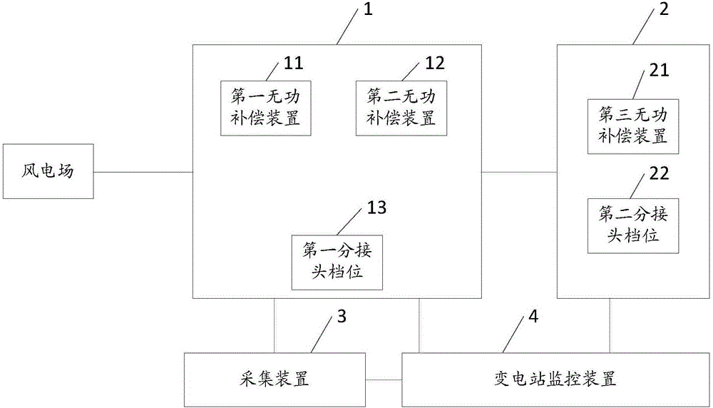
[0039] The core of the present invention is to provide a grid voltage control system and method for wind power generation, which can improve the voltage and reactive power adjustment capability of the grid and reduce the investment of reactive power compensation equipment when the transmission line from wind power to the substation is long. cut frequency.

[0040] In order to make the above objects, features and advantages of the present invention more comprehensible, the specific implementation manners of the present invention will be described in detail below in conjunction with the accompanying drawings.

[0041] In the following description, specific details are set forth in order to provide a thorough understanding of the present invention. However, the present invention can be implemented in many other ways than those described here, and those skilled in the art can make similar extensions without departing from the connotation of the present invention. Accordingly, the...


PUM


Abstract

The invention discloses a power network voltage regulation and control system and method for wind power generation. The system comprises a first reactive power compensation device, a second reactive power compensation device, a third reactive power compensation device, a first tap gear, a second tap gear, a collection device and a substation monitoring device, wherein the first reactive power compensation device is arranged on a high-voltage side bus of a regional master station connected with a wind power plant; the second reactive power compensation device is arranged on a medium-low voltage side bus of the regional master station; the third reactive power compensation device is arranged on a medium-low voltage side bus of a regional slave station connected with the regional master station; the first tap gear is located on the regional master station; the second tap gears are located on the regional slave station; the collection device is used for collecting a voltage parameter and a power factor parameter in a wind power grid; and the substation monitoring device is used for controlling the corresponding tap gears and / or reactive power compensation devices to be switched according to the voltage parameter and the power factor parameter collected by the collection device. The reactive power adjustment ability of the regional power grid is improved under the condition that a power transmission line from wind power to a substation is relatively long; and the switching frequencies of the reactive power compensation devices are reduced.

Description

technical field [0001] The invention relates to the field of grid control, in particular to a grid voltage regulation system and method for wind power generation. Background technique [0002] With the increasingly prominent problems of global warming and shortage of coal resources, wind power generation, as one of the clean energy sources, has attracted people's attention. [0003] However, with the large-scale grid-connected power generation of wind power, many problems have emerged. The uncertainty of wind power generation has a great impact on the reactive power and voltage of the power grid system. At present, in order to improve the reliability and economy of the power grid, the automatic voltage control device is usually concentrated on a single side to perform independent reactive power compensation and voltage regulation on a certain point. Our country adopts the traditional nine-zone map strategy for bus voltage compensation, and selects and controls transformers,...

Claims


Application Information

Patent Timeline
Patent Type & Authority Applications(China)
IPC IPC(8): H02J3/16
CPCH02J3/16Y02E40/30
Inventor 任会生肖凤军姚国良蔡博单学坤韩卓伟马丽娜卢浩然吕健邦柳泉白帆耿云秀亢可
Owner STATE GRID CORP OF CHINA
Why Eureka
Try Eureka