
Gas-liquid distributor for fluidized bed reactor

A fluidized bed reactor, gas-liquid distributor technology, applied in chemical instruments and methods, chemical/physical processes, etc., can solve the problems of catalyst deposition, collision damage of spheres and valve cores, and difficulty in replacing check balls, etc. Turbulence degree and mass transfer efficiency, easy maintenance and cleaning, convenient loading and unloading cleaning effect

Active Publication Date: 2017-01-04
SINOPEC ENG +1
View PDF4 Cites 3 Cited by
  • Summary
  • Abstract
  • Description
  • Claims
  • Application Information

AI Technical Summary

Problems solved by technology

This gas-liquid distributor mainly has the following problems during use: (1) The top of the inner cavity of the valve core is closed, and the gas and liquid entering between the floating check ball and the top of the inner cavity of the valve core will form a swirling flow (gas (2) When the non-return ball is in the normal floating position, if the gas-liquid feed is suddenly interrupted or the pressure The material in the fluidized bed will enter the inner cavity of the valve core below the check ball from the fluid outlet, causing the check ball to fail to quickly fall back to the sealing position to achieve sealing due to the instantaneous pressure of the reverse flow material below.
[0004] Chinese patent CN202478907 discloses a gas-liquid distributor for ebullated bed reactors, which improves the problem of the check ball bouncing up and down in the gas-liquid flow and cannot quickly fall back to the sealing position, but still has the following problems: (1) The inner diameter and wall thickness of the upper, middle and lower sections of the rising pipe are different, making it difficult to manufacture and assemble; (2) Since the upper opening of the rising pipe is sealed by the connecting plate, the coking inside the pipe is not easy to clean, and the check ball is worn out. Difficult to replace; (3) Bolts and nuts are designed on the top of the flat bubble cap, and the nut part above the bubble cap is easily attached by oil gas and catalyst particles, resulting in serious catalyst deposition and coking

Method used


Image

  • Gas-liquid distributor for fluidized bed reactor
  • Gas-liquid distributor for fluidized bed reactor
  • Gas-liquid distributor for fluidized bed reactor

Examples


Embodiment Construction

[0027] The specific embodiments of the present invention will be described in detail below in conjunction with the accompanying drawings, but it should be understood that the protection scope of the present invention is not limited by the specific embodiments.

[0028] Unless expressly stated otherwise, throughout the specification and claims, the term "comprise" or variations thereof such as "includes" or "includes" and the like will be understood to include the stated elements or constituents, and not Other elements or other components are not excluded.

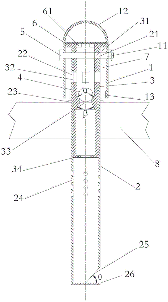
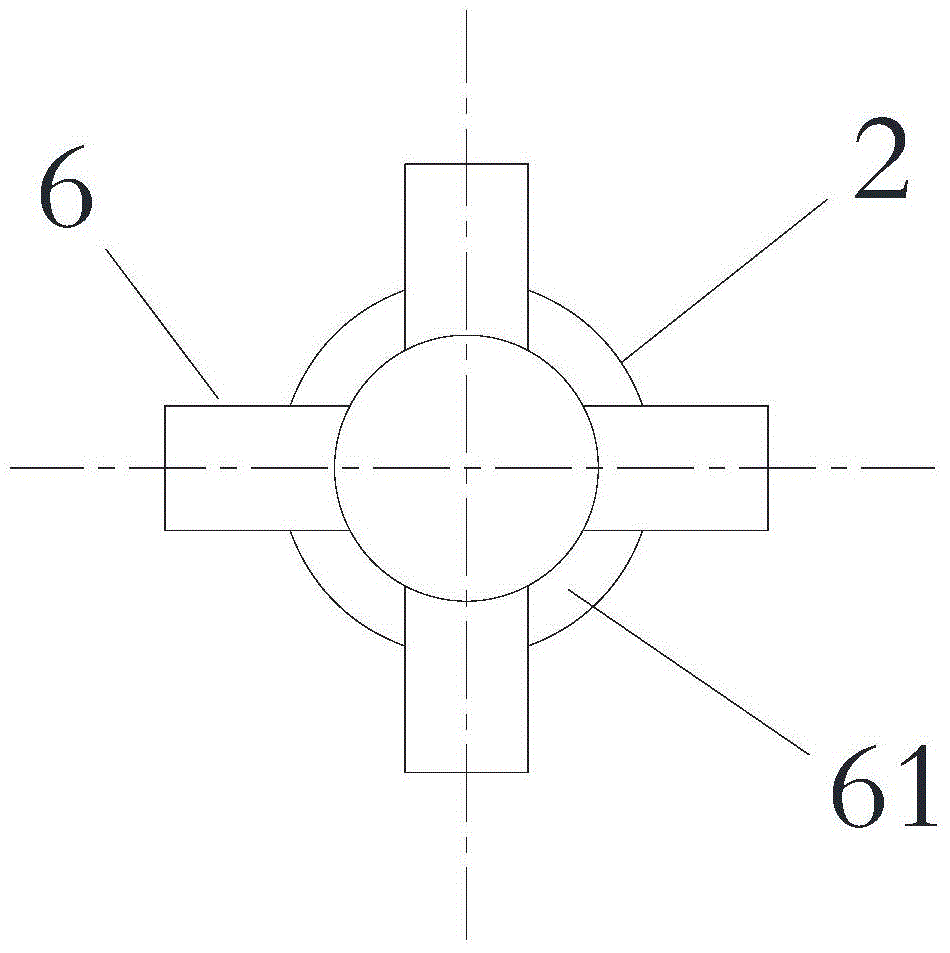
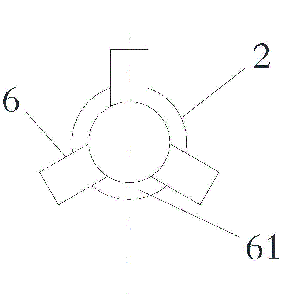
[0029] Such as figure 1 As shown, a gas-liquid distributor for an ebullated bed reactor according to a specific embodiment of the present invention includes: an outer pipe 2, an inner pipe 3, a check ball 4 and a bubble cap 1, wherein the outer pipe 2 includes an upper section And the lower section, the tube wall of the lower section is provided with an air inlet 24, and the tube wall of the upper section is provided with ...


PUM


Abstract

The invention discloses a gas-liquid distributor for a fluidized bed reactor. The gas-liquid distributor comprises an outer pipe, an inner pipe, a non-return ball and a bubble cap, wherein the outer pipe comprises an upper-section part and a lower-section part, the pipe wall of the lower-section part is provided with a gas inlet and the pipe wall of the upper-section part is provided with an outer pipe opening; the middle position in the inner pipe is provided with a diameter-variable channel; the lower port of the inner pipe is provided with a pore plate, and the pipe wall of the upper end part of the inner pipe is provided with an inner pipe opening; when the inner pipe is inserted in the upper-section part of the outer pipe, the inner pipe and the upper-section part form a sleeve part; the inner pipe opening is aligned with the outer pipe opening to form a gas passing channel; the non-return ball is located on the upper end of the diameter-variable channel and is hermetically matched with the hole wall of the diameter-variable channel; and the bubble cap sleeves the outer side of the sleeve part, an annular channel is formed by enclosure of the bubble cap and the outer wall of the upper-section part, and the lower end of the bubble cap is provided with an opening. The gas-liquid distributor is uniform in gas-liquid mixing, greatly flexible in operation, simple and rational in structure and safe and durable to use.

Description

technical field [0001] The invention relates to the field of material distribution in petrochemical industry, in particular to a gas-liquid distributor for a fluidized bed reactor. Background technique [0002] Ebullated bed technology has the advantages of small bed layer pressure, uniform reaction temperature, no clogging and easy heat extraction, etc. It is widely used in petrochemical and environmental protection fields. With the intensification of heavy and inferior crude oil worldwide, the fluidized bed process has great advantages in the field of hydrogenation of residual oil with high viscosity and many impurities. The basic principle of this process is that the solid catalyst particles in the reactor in the fluidized bed are in an irregular motion state, relying on the bottom-up flow of the gas phase and liquid phase to maintain the boiling state, so that the gas phase and the liquid phase can reach a more sufficient contact. . In the ebullated bed reactor, the ga...

Claims


Application Information

Patent Timeline
Patent Type & Authority Applications(China)
IPC IPC(8): B01J8/22
Inventor 乔爱军范传宏吴德飞李浩杨玖坡张迅
Owner SINOPEC ENG
Learn More