Centrifugal micro-fluidic control chip

A microfluidic chip and centrifugal technology, applied in fluid controllers, laboratory utensils, laboratory containers, etc., can solve the problems of difficult to realize siphon valves, and achieve the effect of wide application prospects.

Active Publication Date: 2017-01-04
CAPITALBIO CORP +1
View PDF6 Cites 17 Cited by
  • Summary
  • Abstract
  • Description
  • Claims
  • Application Information

AI Technical Summary

Problems solved by technology

However, processes such as nucleic acid amplification and immunoassay usually require complex fluid operations such as multi-step addition or flow of liquid, and the above-mentioned siphon valve is difficult to realize

Method used


Image

  • Centrifugal micro-fluidic control chip
  • Centrifugal micro-fluidic control chip
  • Centrifugal micro-fluidic control chip

Examples


specific Embodiment 1

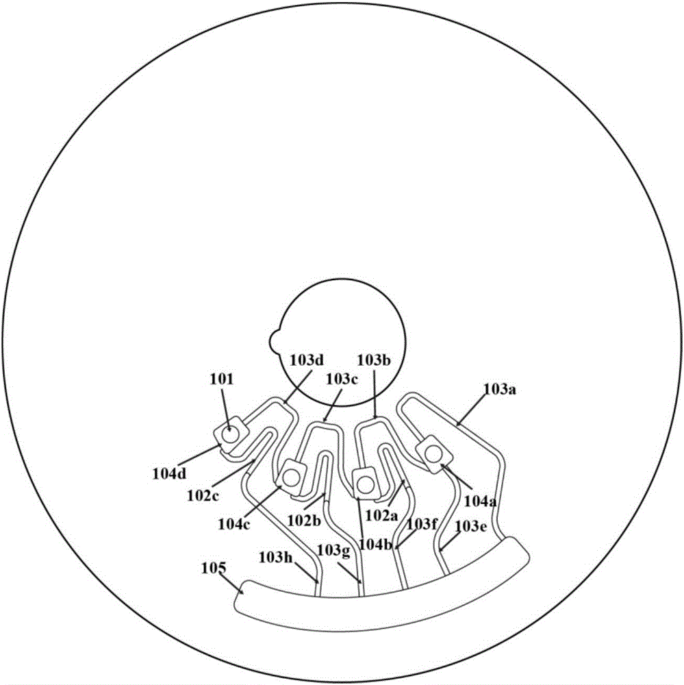
[0034] Sample injection hole 101, first siphon (102a, 102b, 102c), first connecting pipe (103a and 103e), second connecting pipe (103b, 103c and 103d), fifth connecting pipe (103f, 103g and 103h), Sample loading chamber (104a, 104b, 104c and 104d), collection chamber 105, such as figure 1 As shown, in order to distinguish the various components, in this embodiment, the components of the same structure are only distinguished by different numbers, and the content in parentheses behind the components is the same component with different numbers, so as to facilitate review.

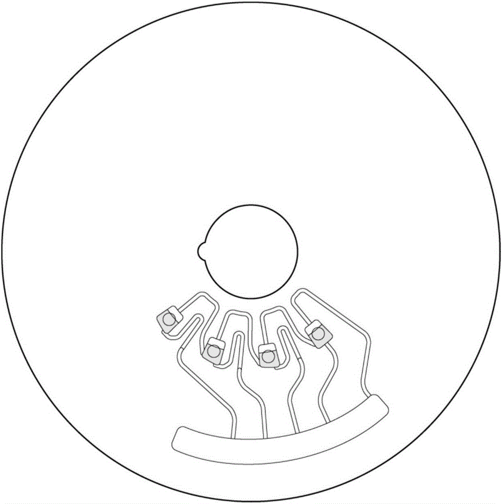
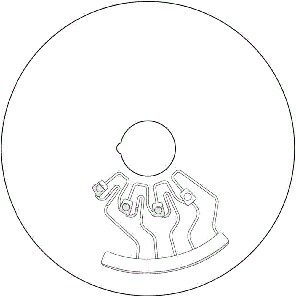
[0035] Wherein, the first siphon tube 102a, the first siphon tube 102b and the first siphon tube 102c are all hydrophilically modified, and the second connecting tube 103b, the second connecting tube 103c and the second connecting tube 103d are hydrophobically modified. During the experiment, add water from the sample hole into the corresponding sample chamber, such as Figure 2a As shown in the figure, it c...

specific Embodiment 2

[0037] Sample injection hole 301, first siphon (302a, 302c), second siphon (302b, 302d), first connecting pipe (303a and 303b), second connecting pipe (303c and 303d), third connecting pipe (303f) , the fourth connecting pipe (303g), the fifth connecting pipe (303e), the sample adding chamber (304a, 304b and 304c), the mixing chamber 305, the collecting chamber (306a, 306b), such as image 3 As shown, in order to distinguish the various components, in this embodiment, the components of the same structure are only distinguished by different numbers, and the content in parentheses behind the components is the same component with different numbers, so as to facilitate review.

[0038] Among them, the first siphon 302a, the first siphon 302c and the second siphon 302d are hydrophilically modified, only the part of the second siphon 302b close to the collection chamber 306a is hydrophilicly modified, and the second connecting pipe 303d is hydrophobically modified. During the experi...

specific Embodiment 3

[0040] Sample injection hole 501, first siphon (502a, 502c), second siphon (502b, 502d), first connecting pipe (503a and 503b), second connecting pipe (503c and 503d), third connecting pipe (503f) , the fourth connecting pipe (503g), the fifth connecting pipe (503e), the sample adding chamber (504a, 504b and 504c), the mixing chamber 505, the collecting chamber (506a, 506b), such as Figure 5 As shown, in order to distinguish the various components, in this embodiment, the components of the same structure are only distinguished by different numbers, and the content in parentheses behind the components is the same component with different numbers, so as to facilitate review.

[0041] Wherein, the first siphon tube 502c and the second siphon tube 502d are hydrophilically modified, the first siphon tube 502a and the second siphon tube 502b are not hydrophilically modified, and the second connecting tube 503d is hydrophobically modified. The liquid operation process is similar to ...


PUM


Abstract

The invention discloses a centrifugal micro-fluidic control chip. Sample adding chambers are connected with first siphon pipes, and each two adjacent sample adding chambers are connected through a second connecting pipe, so that liquid in the sample adding chambers can block airways in other sample adding chambers or at one ends or two ends of the first siphon pipes corresponding to the sample adding chambers; flowing-out or moving of the liquid in the sample adding chambers causes ventilation condition change of other sample adding chambers and the corresponding first siphon pipes, so that liquid in other sample adding chambers can fill the first siphon pipes, and the liquid in multiple sample adding chambers is enabled to sequentially flow into a first cavity. By combining multiple fluid control structures based on condition siphon, complex fluid operation like enabling liquid on the centrifugal micro-fluidic control chip to sequentially be added into or flow out can be realized, so that the centrifugal micro-fluidic control chip has wide application prospect in the fields of biology, chemistry and medicine.

Description

technical field [0001] The invention relates to a centrifugal microfluidic chip in the technical field of chemical equipment. Background technique [0002] Microfluidic chip technology is a technology that integrates the basic operations of sample preparation, separation, reaction and detection in various biological, chemical or medical analysis processes on chips ranging from a few square centimeters to tens of square centimeters. With the characteristics of integration, automation, and small consumption of samples and reagents, it has been widely used in biochemical detection, nucleic acid amplification, immunoassay, cell sorting, food safety and environmental monitoring and other fields. [0003] The siphon valve is a commonly used valve structure on centrifugal microfluidic chips, which can realize the quantification and release of liquid on the chip. The working process of the siphon valve is: when the chip rotates at low speed or stops rotating, the liquid fills the s...

Claims


Application Information

Patent Timeline
Patent Type & Authority Applications(China)
IPC IPC(8): B01L3/00
CPCB01L3/5027B01L2300/087B01L2300/16B01L2400/0409
Inventor 孟详睿徐友春朱芸增陈一奇邢婉丽程京
Owner CAPITALBIO CORP
Why Eureka
Try Eureka