Annular fluidized bed separator of particle mixture

An annular flow, fluidized bed technology, applied in solid separation, separation of solids from solids by gas flow, chemical instruments and methods, etc. problems, to achieve the effect of improving separation efficiency, optimizing structure size, and high-efficiency separation

Active Publication Date: 2017-01-04
TSINGHUA UNIV
View PDF7 Cites 8 Cited by
  • Summary
  • Abstract
  • Description
  • Claims
  • Application Information

AI Technical Summary

Problems solved by technology

The separation process still has the problem of low particle separation efficiency. The main reason is that the particle group is not fully dispersed in the classifier, and the collision between particles is relatively severe, thereby reducing the separation effect of the classifier.

Method used


Image

  • Annular fluidized bed separator of particle mixture
  • Annular fluidized bed separator of particle mixture
  • Annular fluidized bed separator of particle mixture

Examples


Embodiment 1

[0057] Ore enrichment and flotation: separation of ilmenite particles and light particles at room temperature.

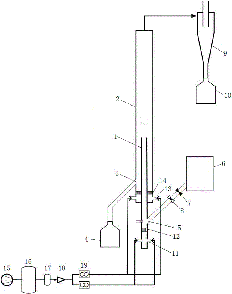
[0058] figure 1 Shown is an annular fluidized bed separator for particle mixture, the upper end of the central riser 1 extends from the bottom surface of the annular fluidized bed 2 to a certain height inside the annular fluidized bed 2, so that the annular fluidized bed 2 is divided into the lower part Annular area 101 and upper cylindrical area 102; the bottom of central riser 1 and annular fluidized bed 2 are respectively provided with central riser air inlet 11 and annular fluidized bed air inlet 13, and in central riser 1 and annular fluidized bed Inside the fluidized bed 2, a central riser air distribution plate 12 and an annular fluidized bed air distribution plate 14 are respectively arranged above the respective air inlets.

[0059] At the bottom of the central riser 1, at a certain height above the air distribution plate 12 of the central riser, there is ...

Embodiment 2

[0073] Gas-solid reaction process involving two kinds of particles: continuous and rapid separation at high temperature.

[0074] Reactor system such as Figure 4 As shown, the upper end of the central riser 1 extends vertically into the annular fluidized bed 2 to a certain height, so that the annular fluidized bed 2 is divided into a lower annular area 101 and an upper cylindrical area 102 . The lower end of the central riser 1 is connected to a buffer tank 21, and the feed port of the buffer tank 21 communicates with the solid phase outlet of the reactor 20 through a connecting pipe. The gas outlet at the top of the annular fluidized bed 2 is connected to the top of the reactor 20, and the gas outlet at the upper side wall of the reactor 20 is connected to the first cyclone separator 9, and the particle outlet of the cyclone separator 9 passes through a U-shaped return valve 23 The light particle return port connected to the side wall of the reactor 20.

[0075] At the bot...


PUM


Abstract

The invention relates to an annular fluidized bed separator of a particle mixture. The upper end of a center lifting pipe extends into an annular fluidized bed by a certain height, so that the annular fluidized bed is divided into an annular area at the lower part and a cylindrical area at the upper part; an air inlet and a wind distribution plate are respectively arranged at the bottoms of the center lifting pipe and the annular fluidized bed; a feed port is formed in the bottom of the center lifting pipe; a heavy particle outlet is formed in the bottom of an annular area of the annular fluidized bed, and is connected with a heavy particle collecting tank; and an airflow outlet at the top of the annular fluidized bed is connected to a light particle collecting tank by a cyclone separator. The particle mixture is quickly fluidized in the center lifting pipe for primary dispersion, and is ascended along with air currents to enter the annular fluidized bed for secondary dispersion. The annular fluidized bed separator can continuously and quickly perform high-efficiency separation for light and heavy particle mixtures under the condition of normal temperature or high temperature. The annular fluidized bed separator can be coupled with a circulating fluidized bed reactor system, and can continuously and stably operate.

Description

technical field [0001] The invention belongs to the technical field of particle mixture separation, in particular to an annular fluidized bed separator for particle mixture. Background technique [0002] Separation devices for particle mixtures can be divided into mechanical and non-mechanical types. [0003] Mechanical separators, such as vibrating screen machines, etc. The principle of vibrating sieve is to use vibration to provide separation energy, and to separate particles of different particle sizes through the screen. The cost is low and the process is simple, but it cannot separate two kinds of particles with similar particle sizes and different particle densities. In addition, the screening is not sufficient , long-term vibration drying, easy to cause particle breakage. Other types of mechanical separators are mainly based on the particle size and density of the particles, and the particles are separated by centrifugation. Generally speaking, mechanical particle ...

Claims


Application Information

Patent Timeline
Patent Type & Authority Applications(China)
IPC IPC(8): B07B7/01B07B9/02B07B11/02
CPCB07B7/01B07B9/02B07B11/02
Inventor 李振山蔡宁生成茂
Owner TSINGHUA UNIV
Why Eureka
Try Eureka