Pipe limiting point forming clamp

A technology of limit points and pipe fittings, which is applied in the direction of manufacturing tools, auxiliary devices, auxiliary welding equipment, etc., can solve the problems such as the inability to guarantee the consistency of the insertion depth of pipe fittings, the inability to guarantee the welding strength, and the uneven gap between the insertion interfaces. Good performance, good product appearance, and the effect of improving product quality

Active Publication Date: 2017-01-04
陕西宝成-爱罗泰齐空调设备有限公司
View PDF6 Cites 2 Cited by
  • Summary
  • Abstract
  • Description
  • Claims
  • Application Information

AI Technical Summary

Problems solved by technology

[0002] The traditional key plug-in connection has the following defects: ①The traditional plug-in connection of pipe fittings is to directly insert a line on the pipe fittings, observe the insertion depth with eyes, and then clamp the pipe fittings with pliers to fix them, so that the insertion depth of the pipe fittings Consistency cannot be guaranteed, and product quality cannot be controlled; ②The traditional way of plugging and fixing pipe fittings is fixed by pipe fitting deformation (clamp flattening)
The inner diameter of the pipe fittings in the plug-in section changes greatly. When the medium passes through the pipe fittings in the plug-in section, the instantaneous flow rate of the medium is affected by the change in the inner diameter of the pipe fittings, which affects the performance of the product; ③The traditional pipe fittings have uneven gaps on the circumference of the socket , due to the deformation of the pipe fittings, the gaps on the circumference of the pipe fittings are different in size, and the uneven gap during the welding process will cause uneven solder filling, and the welding strength cannot be guaranteed, which will affect the welding quality; in summary, it is necessary to improve

Method used


Image

  • Pipe limiting point forming clamp
  • Pipe limiting point forming clamp
  • Pipe limiting point forming clamp

Examples


Embodiment Construction

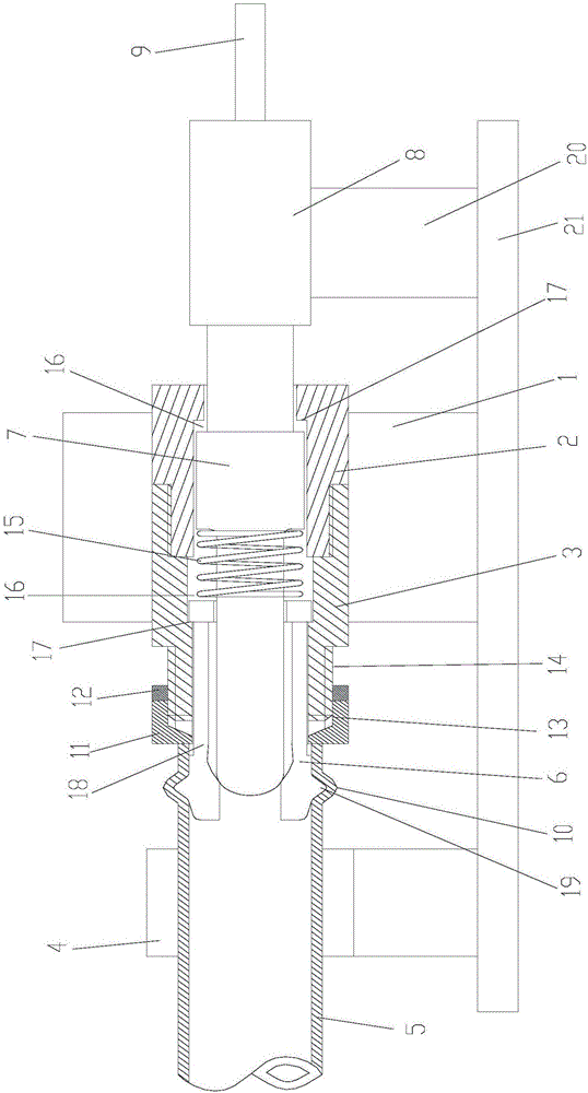
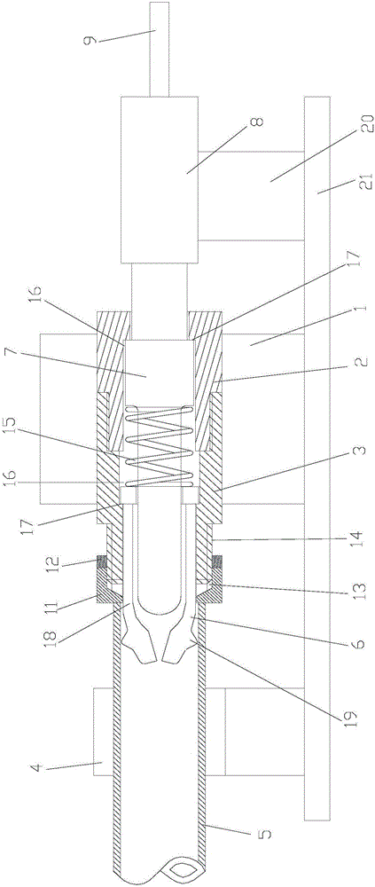
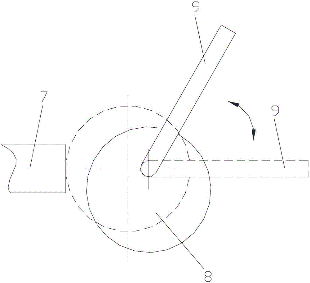
[0016] Attached below Figure 1-3 An embodiment of the present invention is described.

[0017] The pipe limit point forming fixture has a mounting seat 1, and the mounting seat 1 is provided with a fixed part 2 and a connecting part 3 connected to each other. The depth adjustment part is arranged at the left end of the connecting part 3 and is fixedly connected with the connecting part 3. The forming device The spring head 6 at the left end and the mandrel 7 at the right end of the forming device are arranged inside the fixing part 2 and the connecting part 3, respectively pass through and protrude from the depth adjustment part and the fixing part 2, and then place outside it. The part of the depth adjustment part is inserted into the pipe hole at the right end of the pipe part 5, which is located on the left side of the depth adjustment part and against the left end surface of the depth adjustment part. The wheel 8 is in contact with the mandrel 7, the handle 9 is fixedly ...


PUM


Abstract

The invention provides a pipe limiting point forming clamp which is provided with an installation base. A fixing part and a connecting part which are connected are arranged on the installation base. A forming device is arranged in the fixing part and the connecting part, a spring head at the left end of the forming device penetrates and stretches out of a depth adjusting part to be arranged at the outer portion of the depth adjusting part, and a central spindle at the right end of the forming device penetrates and stretches out of the fixing part to be arranged at the outer portion of the fixing part. The part, stretching out of the depth adjusting part, of the spring head is inserted in the left side of the depth adjusting part and abuts against the interior of a pipe hole in the right end of a pipe on the left end face of the depth adjusting part. A handle is fixedly connected with an eccentric wheel, the eccentric wheel pushes the central spindle to move leftwards or rightwards by rotating the handle, then the spring head is controlled to be opened or closed, and therefore forming of a limiting bump on the pipe is achieved. According to the pipe limiting point forming clamp, it can be ensured that welding gaps are uniform in the inserting connecting and welding process of a flow diversion pipe of a heat exchanger, operation is simple, efficiency is high, consistency of the insertion connecting depth of the product can be effectively ensured, the product quality is improved, the product appearance is good, the insertion connecting depth size range of the pipe is adjustable, and the pipe limiting point forming clamp is suitable for different work occasions.

Description

technical field [0001] The invention relates to a clamp, in particular to a clamp for forming a limit point of a pipe fitting. Background technique [0002] The traditional key plug-in connection has the following defects: ①The traditional plug-in connection of pipe fittings is to directly insert a line on the pipe fittings, observe the insertion depth with eyes, and then clamp the pipe fittings with pliers to fix them, so that the insertion depth of the pipe fittings Consistency cannot be guaranteed, and product quality cannot be controlled; ②The traditional way of plugging and fixing pipe fittings is fixed by pipe fitting deformation (clamp flat). The inner diameter of the pipe fittings in the plug-in section changes greatly. When the medium passes through the pipe fittings in the plug-in section, the instantaneous flow rate of the medium is affected by the change in the inner diameter of the pipe fittings, which affects the performance of the product; ③The traditional pip...

Claims


Application Information

Patent Timeline
Patent Type & Authority Applications(China)
IPC IPC(8): B23K37/053
CPCB23K37/0531
Inventor 杨璟
Owner 陕西宝成-爱罗泰齐空调设备有限公司
Why Eureka
Try Eureka