
Three-chamber structure small-test filter-press analog device

A simulation device and pressure testing technology, which is applied in the fields of dehydration/drying/concentrated sludge treatment, water/sludge/sewage treatment, chemical instruments and methods, etc., can solve problems such as inconvenient operation, high cost, and low efficiency, and achieve Improved filter press effect, convenient operation and high efficiency

Inactive Publication Date: 2017-01-04
SAFECLEEN TECH
View PDF5 Cites 1 Cited by
  • Summary
  • Abstract
  • Description
  • Claims
  • Application Information

AI Technical Summary

Problems solved by technology

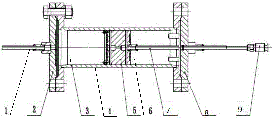
[0003] However, in the actual test process, the following problems were found in the existing small test filter press simulation device: 1) After the filter press is completed and the mud cake is taken out, it is necessary to manually knock the piston head to push it to the initial position, which is inconvenient to operate and low in efficiency ; 2) When working, the cross-sectional area on both sides of the piston 5 is the same. In terms of power, the pressure filter effect can only be improved by increasing the pressure of the air source, and the cost is high; 3) The inner drain pipe 7 is a hose. Due to the influence of extrusion, etc., the sealing performance will be deteriorated, causing the air source in the pressurization chamber 6 to leak, which will affect the filter press effect; 4) The thickness data of the mud cake cannot be obtained directly after the filter press, and the mud cake needs to be taken out to measure, and The volume difference of the press filter cannot be obtained directly

Method used


Image

  • Three-chamber structure small-test filter-press analog device
  • Three-chamber structure small-test filter-press analog device
  • Three-chamber structure small-test filter-press analog device

Examples


Embodiment Construction

[0019] The present invention will be further described below in conjunction with the accompanying drawings and embodiments.

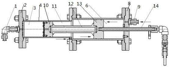
[0020] like figure 2 As shown, a three-chamber small test filter press simulation device includes a detachable sealed casing 4 at both ends (the two ends of the casing 4 are the front end cover 2 and the rear end cover 8 respectively), and the casing 4 is covered by the first piston. 10 and the second piston 13 are divided into a working chamber 3, an intermediate chamber 11 and a pressurized chamber 6 which are arranged in a straight line, filter cloths are arranged on the side walls of both ends of the working chamber 3, and the two ends of the working chamber 3 are respectively It communicates with the drain channel on the outer drain pipe 1 and the first piston 10, the first piston 10 and the second piston 13 are connected by a rigid first inner drain pipe 12, and the first inner drain pipe 12 is connected with the first piston 10 and the first pis...


PUM


Abstract

The invention relates to a three-chamber structure small-test filter-press analog device. The three-chamber structure small-test filter-press analog device comprises a sealed housing with two detachable ends, wherein the housing is divided into a working chamber, a middle chamber and a pressurizing chamber which are straightly arranged in sequence by a first piston and a second piston; filter cloth is arranged on the side walls of two ends of the working chamber respectively; the two ends of the working chamber are communicated with an outer drainage pipe and a drainage flow passage on the first piston respectively; the first piston and the second piston are connected through a first rigid inner drainage pipe; the first inner drainage pipe is communicated with drainage flow passages on the first piston and the second piston respectively; a second inner drainage pipe stretches into the pressurizing chamber in a sealing manner to be communicated with the drainage flow passage on the second piston; and high-pressure dielectric joints are arranged on the middle chamber and the pressurizing chamber respectively. The device adopts a three-chamber structure, the pistons after filter pressing is completed can be quickly reset, and the device is convenient in operation and high in efficiency.

Description

technical field [0001] The invention belongs to the field of environmental protection, and in particular relates to a small test filter press simulation device with a three-chamber structure. Background technique [0002] In the field of environmental protection, sludge is often subjected to pressure filtration treatment. Generally, a small test filtration simulation device is used to simulate the filtration process and test the filtration effect. like figure 1 As shown, the existing small test filter press simulation device has a two-chamber structure, and the two chambers are separated by a piston 5, wherein the left end of the working chamber 3 is connected to the outer drain pipe 1, and the pressurized chamber 6 is connected to the pressure source. The piston 5 is provided with a drainage channel, and the inner drain pipe 7 is sealed and extends into the pressurized chamber 6 to communicate with the drainage channel. The left end of the working room 3 and the left end o...

Claims


Application Information

Patent Timeline
Patent Type & Authority Applications(China)
IPC IPC(8): C02F11/12
CPCC02F11/122
Inventor 陈益人刘学进张民傅磊黄蕾刘本森
Owner SAFECLEEN TECH
Learn More