Electrical type balance oil cylinder potential energy recycling system

A technology of balancing oil cylinders and recovering potential energy, which is applied to earth movers/shovels, construction, etc., and can solve the problem of the difficulty in directly releasing the pressure of the hydraulic accumulator, affecting the controllability of the actuator, and the pressure difference change of the actuator speed control valve, etc. problem, to achieve the effect of reducing energy consumption, maintaining the controllability, and reducing power output

Active Publication Date: 2017-01-04
HUAQIAO UNIVERSITY
View PDF6 Cites 10 Cited by
  • Summary
  • Abstract
  • Description
  • Claims
  • Application Information

AI Technical Summary

Problems solved by technology

However, the direct recovery and regeneration of hydraulic accumulators has the following disadvantages: 1) energy can only be stored when the external pressure is higher than the internal pressure of the hydraulic accumulator, and regeneration can only be performed when the internal pressure of the accumulator is higher than its external pressure. And the energy storage and discharge process cannot affect the operating characteristics of the actuator; 2) During the recovery process, the pressure of the hydraulic accumulator will gradually increase, which will cause the pressure difference at both ends of the actuator speed control valve to change, which will inevitably affect The controllability of the actuator; 3) The pressure required by the boom actuator in the drive mode is generally greater than the pressure required in the recovery mode, and the pressure of the hydraulic accumulator is difficult to release directly
Therefore, when energy is recovered from the boom with a balance unit, the hydraulic accumulator is generally used as the energy storage unit, which inevitably has the above-mentioned shortcomings after using the accumulator

Method used


Image

  • Electrical type balance oil cylinder potential energy recycling system
  • Electrical type balance oil cylinder potential energy recycling system
  • Electrical type balance oil cylinder potential energy recycling system

Examples


Embodiment

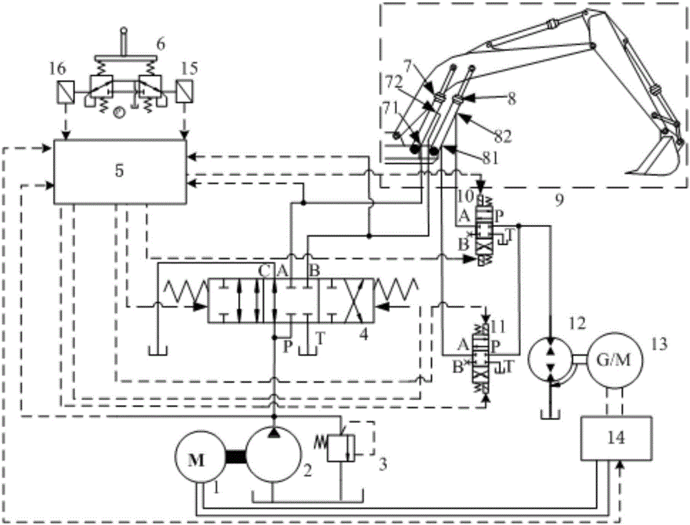
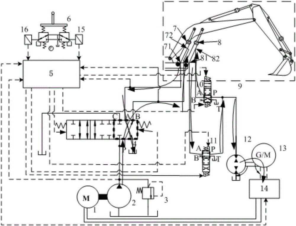
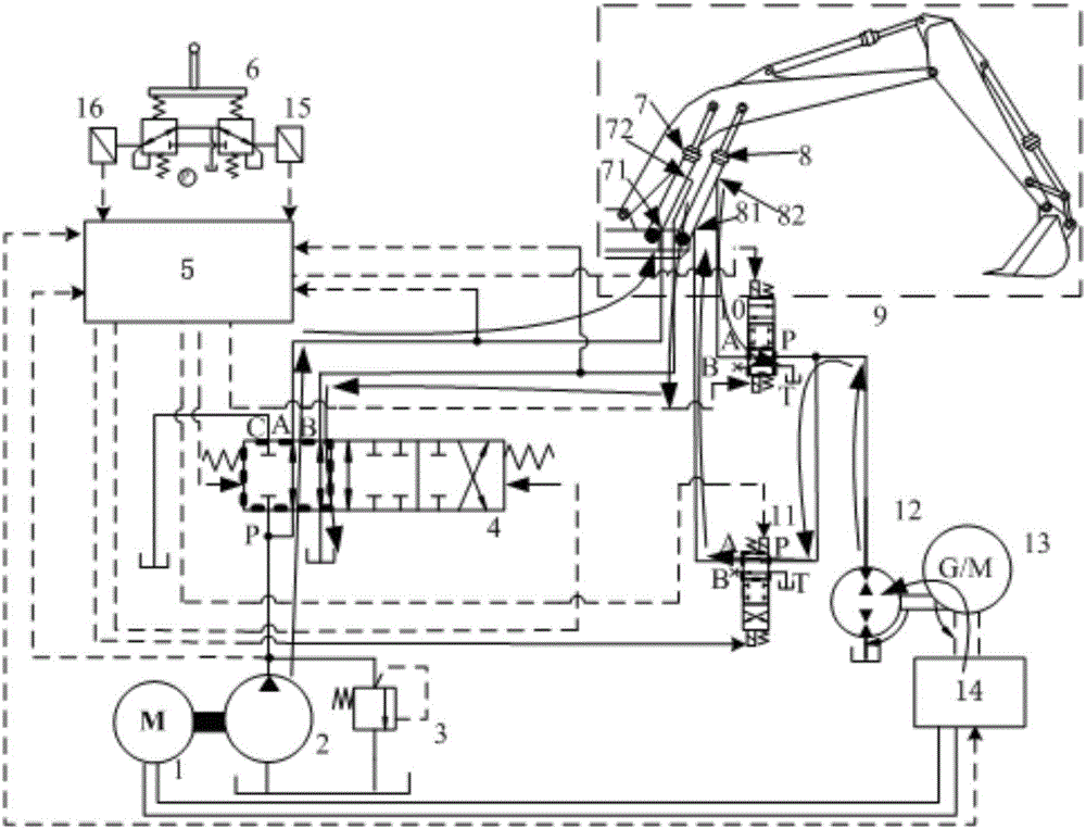
[0028] see figure 1 As shown, an electric balance cylinder 8 potential energy recovery system of the present invention includes a driving motor 1, a hydraulic pump 2 and an original driving cylinder 7, and the original driving cylinder 7 is attached to a boom device 9 of a construction machine. The drive cylinder 7 has a rod chamber 72 and a rodless chamber 71;

[0029] It also includes a balance oil cylinder 8, a controller 5, a two-way hydraulic pump / motor 12, an electric / generator 13 and a power battery 14, the balance oil cylinder 8 is attached to the boom device 9, and the balance oil cylinder 8 is connected to the There is a certain interval between the original driving cylinders 7, and they are arranged symmetrically on both sides of the boom device 9; The power battery 14 is electrically connected; the balance cylinder 8 includes a rod chamber 82 and a rodless chamber 81, the rod chamber 82 of the balance cylinder 8 is connected with the first reversing valve 10, and ...


PUM


Abstract

The invention discloses an electrical type balance oil cylinder potential energy recycling system. On the basis of an original movable arm drive system, a balance oil cylinder, a double-direction hydraulic pump/motor and an electric motor/electric generator are additionally arranged, conversion storage is achieved through the hydraulic pump, the electric motor/electric generator and a power battery, gravitational potential energy of a movable arm device is converted into electric energy to be stored, or the electric energy is converted into hydraulic energy to drive the movable arm to ascend, through control over the rotating speed of the electric motor/electric generator, releasing of electric energy can be controlled, the ascending speed of the movable arm can be controlled, and the defect that in hydraulic energy storage, the releasing process of energy stored in a hydraulic energy accumulator is not controlled is overcome. The electrical type balance oil cylinder potential energy recycling system is suitable for a hydraulic excavator, on the basis of not changing the operation structure of an original power system, gravitational potential energy of the movable arm is stored and released, energy is saved, and the very high economic value is achieved.

Description

technical field [0001] The invention relates to a potential energy recovery system, in particular to an electric balance oil cylinder potential energy recovery system suitable for hydraulic excavators. Background technique [0002] Energy saving and environmental protection are the basic requirements of global economic development for energy devices. Hydraulic excavator, as a kind of construction machinery with a large number of fields, plays an important role in urban construction, mining, road construction and other aspects. However, the problem of high energy consumption of hydraulic excavators has also attracted the attention of researchers, and corresponding research has been carried out on it. At present, the potential energy recovery of hydraulic excavator arms is mainly divided into two types: electric type and hydraulic type. Among them, the electric potential energy recovery and reuse is realized by converting the rodless chamber of the drive cylinder into electr...

Claims


Application Information

Patent Timeline
Patent Type & Authority Applications(China)
IPC IPC(8): E02F9/22
CPCE02F9/2217
Inventor 陈其怀林添良任好玲付胜杰
Owner HUAQIAO UNIVERSITY
Why Eureka
Try Eureka