
Rapid automatic door deceleration device

A technology of deceleration device and automatic door, which is applied in the direction of transmission device, door/window accessories, power control mechanism, etc., can solve the problems of laborious opening of automatic door and low deceleration efficiency, etc. Effect of reduction ratio

Inactive Publication Date: 2017-01-04
SIGMA GIKEN (SHANGHAI) CO LTD
View PDF7 Cites 1 Cited by
  • Summary
  • Abstract
  • Description
  • Claims
  • Application Information

AI Technical Summary

Problems solved by technology

[0004] Aiming at the technical problems of low deceleration efficiency of the automatic door deceleration device in the prior art and laborious opening of the automatic door, the present invention proposes a fast deceleration device for the automatic door

Method used


Image

  • Rapid automatic door deceleration device
  • Rapid automatic door deceleration device
  • Rapid automatic door deceleration device

Examples


Embodiment Construction

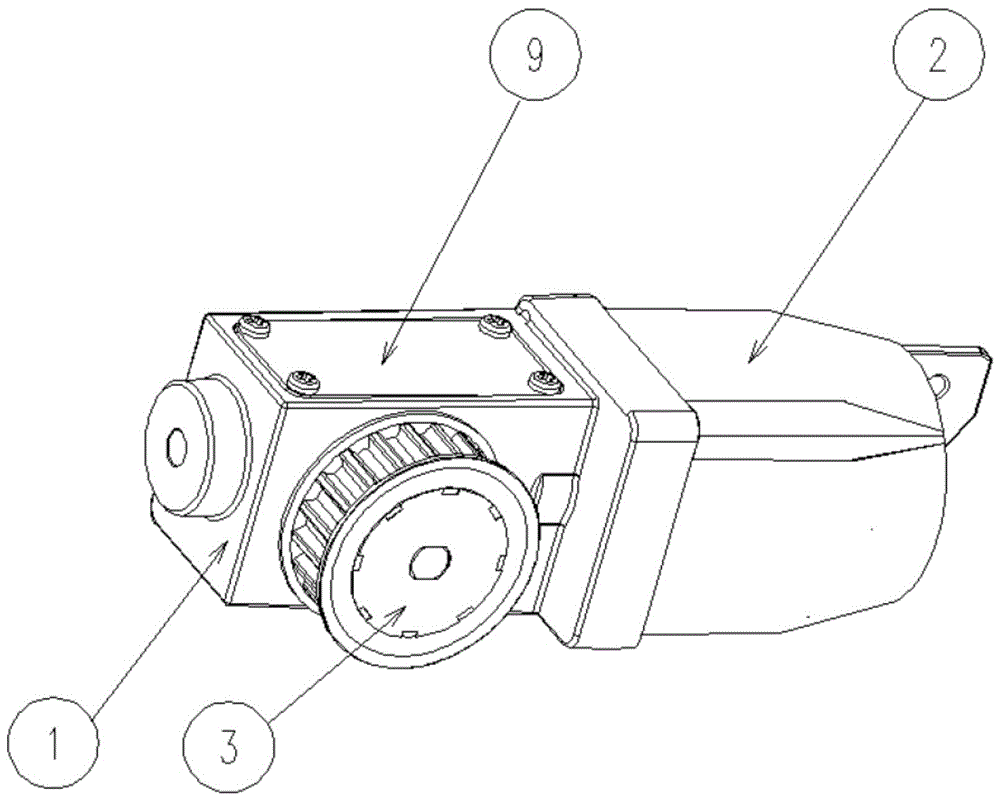
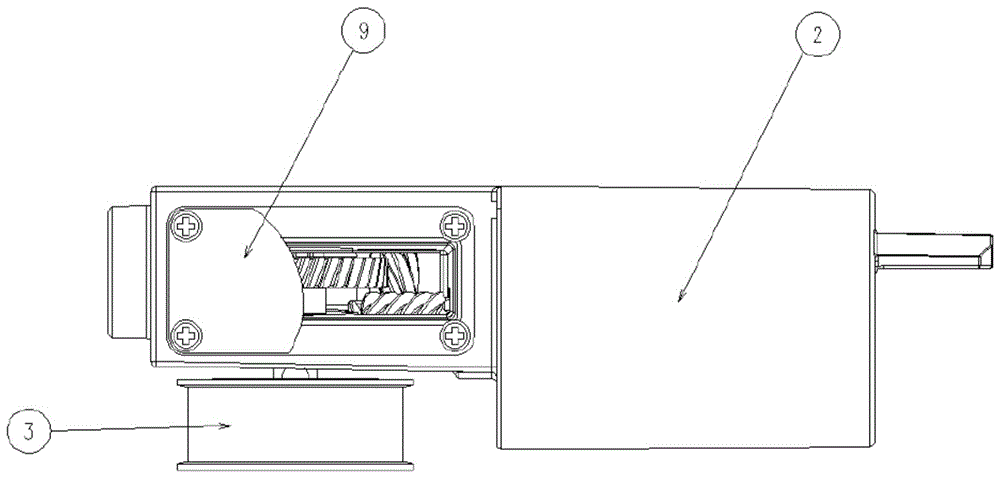
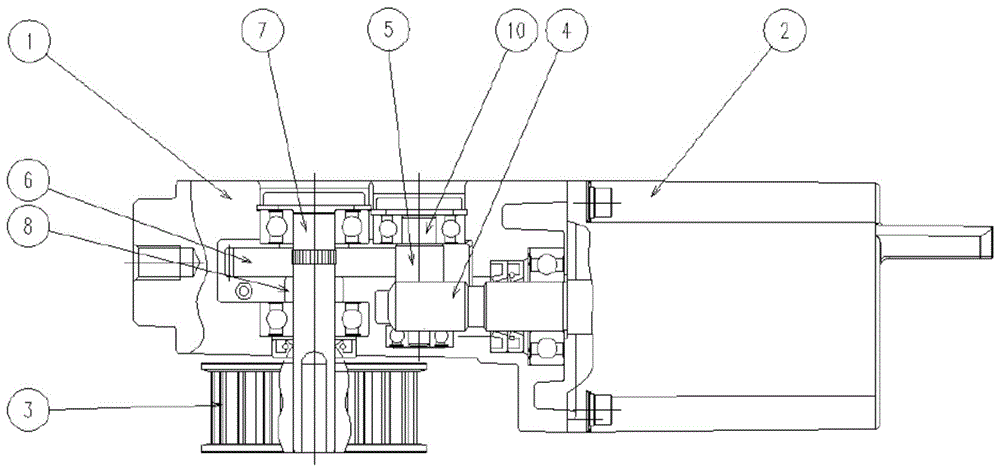
[0021] Such as Figure 1~7 As shown, a fast speed reduction device for automatic doors includes a motor 2 and a gear box 1, wherein: the motor 2 is placed horizontally, the left side of the motor 2 is provided with a gear box 1, the rotor of the motor 2 extends into the inside of the gear box 1 housing, and the motor 2 The end of the rotor is provided with a worm 4, and a gear shaft 10 is arranged perpendicular to the axial direction of the worm 4 and meshed with the worm 4, and a transmission gear 5 is provided on the upper part of the gear shaft 10, and the transmission gear 5 and the gear shaft 10 perform synchronous rotation , the transmission gear 5 transmits power to the pulley drive shaft 7 through the helical gear 6 meshing with it, the axis direction of the pulley drive shaft 7 is parallel to the axis direction of the gear shaft 10, one end of the pulley drive shaft 7 is located inside the gearbox 1, and the other end extends to Outside the gear box 1 , a pulley 3 is ...


PUM


Abstract

The invention discloses a rapid automatic door deceleration device and belongs to the technical field of automatic door deceleration devices. The technical problems that the automatic door deceleration device is low in deceleration efficiency and an automatic door is labor-consuming to open are solved. According to the solution, a gearbox is arranged on one side of a motor; a motor rotor stretches into a gearbox shell; a worm is fixedly arranged at the end of the motor rotor; a gear shaft is meshed with the worm perpendicular to the worm axis direction; a transmission gear is arranged on the upper part of the gear shaft; the transmission gear transmits power to a belt pulley drive shaft through a bevel wheel meshed with the transmission gear; the axis direction of the belt pulley drive shaft is parallel to an axis direction of the gear shaft; and a belt wheel is fixedly arranged on a part, which is positioned on the outer side of the gearbox, of the belt pulley drive shaft. According to the invention, a power transmission system in the gearbox is changed, so that the automatic door is labor-saving to open, a reduction ratio is increased, and the deceleration efficiency of the automatic door deceleration device is improved.

Description

technical field [0001] The invention belongs to the technical field of automatic door deceleration devices, in particular to a fast deceleration device for automatic doors. Background technique [0002] There are many kinds of automatic doors, and many kinds of automatic doors were first used in buildings, which first appeared in the twentieth century. In the late 1920s, with the opening of supermarkets in the United States, automatic doors began to be applied. In 1930, Stanley of the United States launched the world's first automatic door. This historical data was recorded in the New York Times. Afterwards, DORMA, the world's number one automatic door brand, widely introduced hydraulic and air automatic doors to the market in 1945, and automatic doors were also used at the main entrances of new buildings. By 1962, electric automatic doors had begun to appear, and with the construction of cities, the field of automatic door technology was increasing every year. At the beg...

Claims


Application Information

Patent Timeline
Patent Type & Authority Applications(China)
IPC IPC(8): E05F15/603F16H37/02
CPCE05F15/603E05Y2900/132F16H37/02
Inventor 林司
Owner SIGMA GIKEN (SHANGHAI) CO LTD
Learn More