
Economical elevator additionally arranged outside building

An economical and stair technology, which is applied to elevators, transportation and packaging, and vertical pipes in buildings, can solve the problems of increased installation costs, high cost investment, and expensive elevators, and achieve high deceleration efficiency, power saving, and Material saving effect

Inactive Publication Date: 2020-12-15
朱幕松
View PDF7 Cites 0 Cited by
  • Summary
  • Abstract
  • Description
  • Claims
  • Application Information

AI Technical Summary

Problems solved by technology

Since the structure of the old building has been formed, the corridors need to be remodeled when adding elevators, which increases the installation cost, and the elevators in the prior art are very expensive. Therefore, the cost of installing elevators in multiple corridor units of each building is very high. The biggest obstacle to installing elevators in old residential buildings
[0003] The key part of the existing elevator technology is the expensive traction machine, which is related to the safety and reliability of the elevator installed. The traction machine is composed of a motor, a reduction box and a brake, and is the power of the elevator. The motor generally adopts asynchronous induction Type 3-phase AC motor, the gearbox usually adopts the gear box with worm gear transmission. The existing traction machine has the problems of low efficiency and high cost. It is popular and old to adopt a traction machine with simple structure, safety, reliability and low cost. Effective Measures for Adding Elevators to Buildings

Method used


Image

  • Economical elevator additionally arranged outside building
  • Economical elevator additionally arranged outside building
  • Economical elevator additionally arranged outside building

Examples


Embodiment Construction

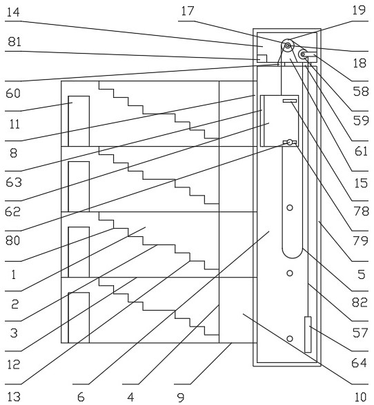
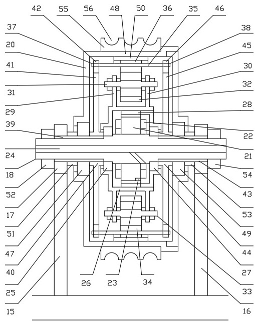
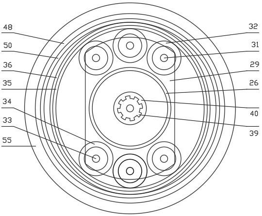
[0012] exist Figure 1-Figure 5 Among them, the old building generally refers to an old-fashioned building with 3 to 6 floors. The old stairs on each floor are provided with a left staircase and a right staircase 1. The directions of the left and right staircases are opposite to each other. Partition wall 2 and half-floor platform 3, elevator shaft is set behind the old building rear wall 4 at the old stair rear end, and described elevator shaft is provided with front wall, rear wall 5, left wall 6 and right wall 7, and elevator shaft front wall A plurality of hoistway doors 8 are provided, and each hoistway door front end is provided with an elevator door platform 9, and the left and right ends of the elevator door platform are all provided with newly-built walls 10, and the newly-built walls are connected with the front wall of the elevator hoistway, and each elevator door platform front end is There are newly-built corridors 12 that lead directly to the door 11 of the resid...


PUM


Abstract

An economical elevator additionally arranged outside a building comprises an old building, an old stair, an elevator shaft, a shaft door, a car, a car door, an elevator door platform, a newly-built walkway, a newly-built stair, an elevator machine room, a harmonic speed reduction traction machine, a traction wheel, a traction guide wheel, a steel wire rope, a car guide wheel, a car guide rail, counterweight iron plates, counterweight guide wheels, counterweight guide rails, Hall sensors, strip-shaped permanent magnets, an intelligent controller and operating buttons; the harmonic speed reduction traction machine is a hub type traction machine integrating a harmonic speed reducer, a two-pole outer rotor brushless permanent magnet direct current motor and the traction wheel; when the two-pole outer rotor brushless permanent magnet direct current motor is shut down, large magnetic resistance exists between a rotor and a stator, a speed reduction ratio of the harmonic speed reducer is large; when the harmonic speed reduction traction machine is shut down, the harmonic speed reduction traction machine has a strong self-locking function which is equivalent to a braking state, a braking system of the traction machine is omitted, the harmonic speed reduction traction machine is simple and cheap, and the safety and the reliability meet the standard requirements.

Description

technical field [0001] The invention relates to the field of elevator construction, in particular to an economical elevator installed outside a building. Background technique [0002] Many multi-storey residential buildings and other old-fashioned old buildings built in the early years were not equipped with elevators, which caused a lot of inconvenience to the daily life of residents, especially for the elderly and people in wheelchairs. With the development of the economy, people are pursuing better living conditions. In recent years, it has become a trend to require the installation of elevators to improve their lives. Since the structure of the old building has been formed, the corridors need to be remodeled when adding elevators, which increases the installation cost, and the elevators in the prior art are very expensive. Therefore, the cost of installing elevators in multiple corridor units of each building is very high. The biggest obstacle to installing elevators in...

Claims


Application Information

Patent Timeline
IPC IPC(8): B66B11/04B66B11/08B66B7/06B66B7/02B66B17/12B66B1/14B66B1/34B66B1/36E04F17/00
CPCB66B1/14B66B1/3415B66B1/36B66B7/022B66B7/06B66B11/004B66B11/008B66B11/0453B66B17/12E04F17/005
Inventor 朱幕松
Owner 朱幕松
Learn More