Spray purification device and method

A purification device and spray head technology, applied in the field of air purification, can solve the problems of lack of air purification equipment and expensive dust removal equipment, and achieve the effects of compact structure, small footprint and high speed reduction efficiency.

Active Publication Date: 2020-09-29
SHANGHAI NO 4 CONSTR
View PDF21 Cites 0 Cited by
  • Summary
  • Abstract
  • Description
  • Claims
  • Application Information

AI Technical Summary

Problems solved by technology

For the lack of air purification equipment that carries dust, especially when the dust is severe, the existing commercial dus

Method used


Image

  • Spray purification device and method
  • Spray purification device and method
  • Spray purification device and method

Examples


Embodiment 1

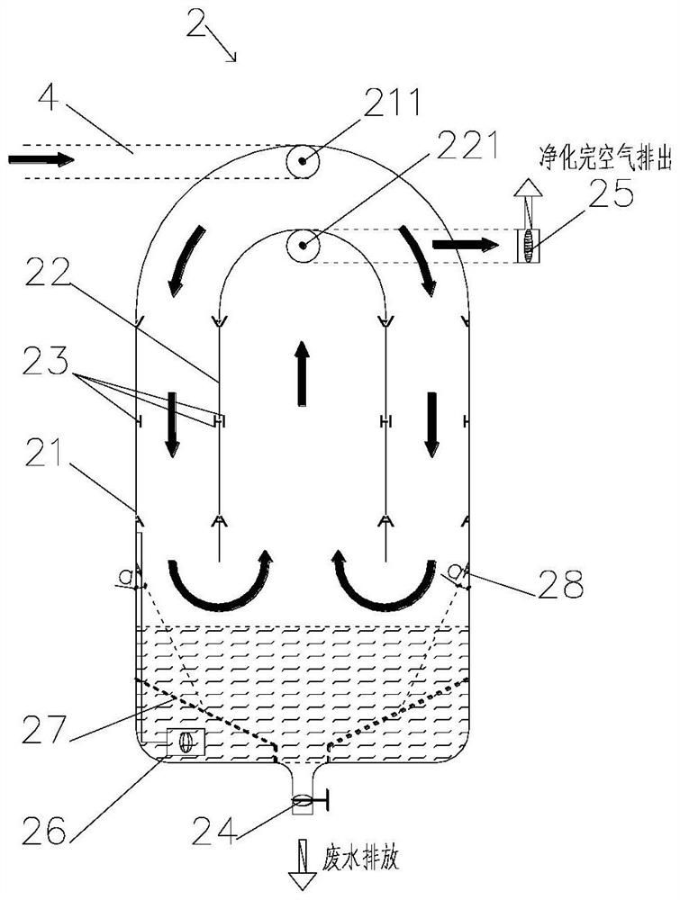
[0040] see figure 1 , the present embodiment provides a spray purification device, including a closed container 21, an inverted container 22 and several pipelines with spray heads 23, the top of the closed container 21 offers an air inlet 211, the closed The bottom of the container 21 is used as a sump, and the bottom of the sump is provided with a first waste water discharge valve 24. The inverted container is an inverted U-shaped structure, and the inverted container 22 is coaxially arranged in the closed container 21. The cross section of the inverted container 22 and the closed container 21 is circular, the top of the inverted container 22 is provided with an exhaust port 221, the bottom of the inverted container 22 is opened, and the gas under pressure with dust is The gas to be treated enters the inside of the closed container 21 through the air inlet 211, passes through the channel between the closed container 21 and the inverted container 22, flows into the inverted co...

Embodiment 3

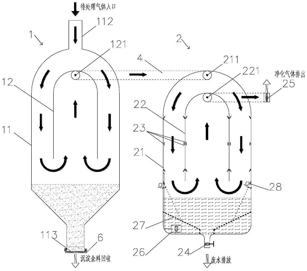
[0054] see Figure 2 to Figure 3 The difference between the pressurized gas purification method provided in the third embodiment and the second embodiment is that, before using the spray purification device 2 to process the dust pressurized gas, that is, the gas to be treated, the gravity sedimentation device 1 is used to expand the volume of the gas to be treated. speed, to precipitate solid particles with a particle size of 10-100 μm in the gas, and the gravity sedimentation device 1 is sealed and connected with the spray purification device 2 through the first pipeline 4 .

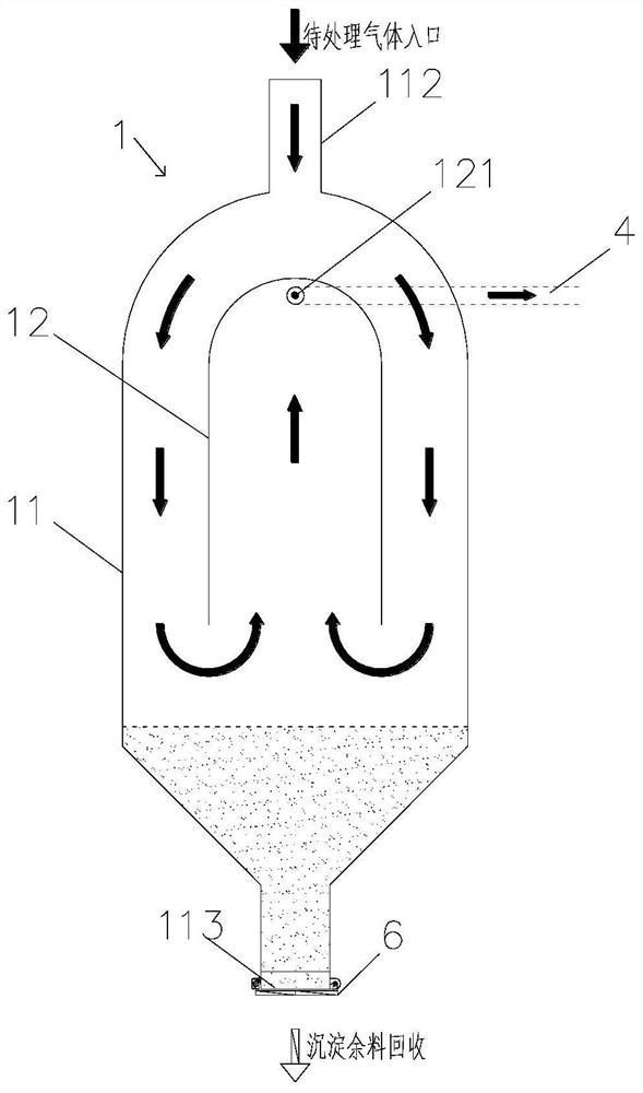
[0055] Preferably, in the above-mentioned spray purification device, the gravity sedimentation device 1 includes a first airtight container 11 and a first inverted container 12, the top of the first airtight container 11 has a first air inlet 112, the The bottom of the first airtight container 11 offers the sedimentation residue recovery port 113, and the first inverted container 12 is an inverted U-sha...

Embodiment 4

[0061] see Figure 5 to Figure 9 , and can be combined with Figure 1 to Figure 4 The difference between the present embodiment and the third embodiment is that the gas treated by the spray purification device 2 is also subjected to liquid-gas combination purification treatment through the liquid dust removal and mixing device 3 chamber, so that the solid particles in the gas are further dissolved in the liquid. The spray purification device 2 is in sealing connection with the liquid dust removal and mixing device 3 through the second pipeline 5, that is to say, the exhaust port 221 is not externally connected with the exhaust valve 25 for discharging the purified gas, but passes through the second pipeline 5 It is sealingly connected with the liquid dust removal and mixing device 3 , that is to say, the spray purification device 2 is sealed and connected with the liquid dust removal and mixing device 3 through the second pipeline 5 .

[0062] The liquid dedusting mixing devi...


PUM

PropertyMeasurementUnit
Particle sizeaaaaaaaaaa

Abstract

The invention belongs to the field of air purification, and provides a spray purification device and method. The device comprises a closed container, an inverted container and a plurality of pipelineswith spray heads. An air inlet is formed in the top of the closed container; the lower part of the closed container serves as a water collecting tank; a first wastewater discharge valve is arranged at the bottom of the water collecting tank; the inverted container is of an inverted U-shaped structure; the inverted container is coaxially arranged in the closed container, an exhaust port is formedin the top of the inverted container, an opening is formed in the bottom of the inverted container, a plurality of pipelines with spray heads are arranged on the inner wall of the closed container andthe inner wall and the outer wall of the inverted container respectively, and water in the water collecting tank is pumped to the spray heads through a pressure pump. The dust-containing pressurizedgas is humidified by the spray head so that solid particles with the particle size of 2.5-10mu m in the dust-containing pressurized gas are precipitated or the dust is dissolved in the water when meeting the water to increase the weight, thereby achieving the purpose of purifying the air.

Description

technical field [0001] The invention relates to the field of air purification, in particular to a spray purification device and method. Background technique [0002] As building a beautiful home has become a national strategy, the control of dust in environmental issues involves the health of every citizen and has become the focus of people's daily life. The construction industry has been included in one of the main battlefields of air pollution prevention and control, and the problem of dust is the core element of control. Dust and pressurized gas emissions from cement silos and mortar silos on the construction site are the hardest hit areas. At present, most of the dust control measures are taken to isolate the polluted air or suggest to cover the pollution sources. The dust pollution prevention and control measures are very effective. For the lack of air purification equipment that carries dust, especially when the dust is severe, the existing commercial dust removal eq...

Claims


Application Information

Patent Timeline
IPC IPC(8): B01D47/06B01D45/02B01D50/00B01D53/18
CPCB01D47/06B01D45/02B01D53/18B01D50/40
Inventor 马晓辉高卫明周君周红兵黄轶周晓莉张铭
Owner SHANGHAI NO 4 CONSTR
Why Eureka
Try Eureka