Electric drive axle system and pure electric operation vehicle using same

A technology for operation and bridge driving, which is applied in the direction of electric vehicles, vehicle parts, electric power devices, etc., can solve the problems of scattered system layout and low degree of integration, and achieve the effects of compact system layout, improved transmission efficiency, and reduced power consumption

Pending Publication Date: 2022-07-12
ZHENGZHOU YUTONG BUS CO LTD
View PDF1 Cites 0 Cited by
  • Summary
  • Abstract
  • Description
  • Claims
  • Application Information

AI Technical Summary

Problems solved by technology

[0010] The purpose of the present invention is to provide an electric drive axle system to solve the technical problems in the prior art that the two motors for driving and working are independently arranged relative to

Method used


Image

  • Electric drive axle system and pure electric operation vehicle using same
  • Electric drive axle system and pure electric operation vehicle using same
  • Electric drive axle system and pure electric operation vehicle using same

Examples


specific Embodiment 1

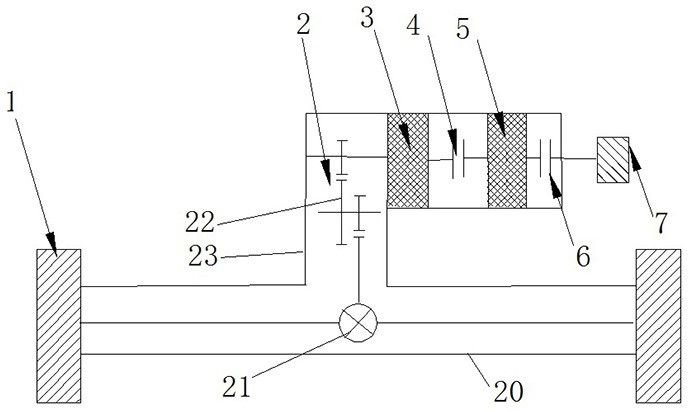
[0088] like figure 2 As shown, the electric drive axle system in this embodiment includes a vehicle axle 2, and the vehicle axle 2 is T-shaped as a whole, including a transverse axle portion 20 and a longitudinal axle portion 23, wherein the transverse axle portion 20 is along the left and right sides of the vehicle body. Extending in the width direction, the longitudinal axle portion 23 extends along the longitudinal direction of the front and rear of the vehicle body, and the wheels 1 are respectively mounted on both ends of the transverse axle portion 20 .

[0089] The axle 2 is provided with an axle main reducer 22 and an axle differential 21 , the axle main reducer 22 is located on the longitudinal axle part 23 , and the output end of the axle main reducer 22 is connected to the axle differential 21 . The power is input, and the axle differential 21 inputs the power to the wheels 1 on both sides through the semi-axes on both sides to drive the wheels 1 to rotate, and the...

specific Embodiment 2

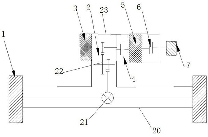
[0107] like image 3 As shown, the electric drive axle system in this embodiment also includes an axle 2, and the axle 2 is also T-shaped, and also has a transverse axle portion 20 and a longitudinal axle portion 23, wherein the transverse axle portion 20 is also along the vehicle axle. The body extends in the left and right width directions, the longitudinal axle portion 23 extends along the longitudinal direction of the vehicle body front and rear, and the wheels 1 are respectively mounted on both ends of the transverse axle portion 20 .

[0108] The axle main reducer 22 and the axle differential 21 are installed on the axle 2. The axle main reducer 22 is located in the longitudinal axle part 23 and is also a two-stage reducer. The axle differential 21 inputs power, and the axle differential 21 inputs the power to the wheels 1 on both sides through the two semiaxes, and drives the wheels 1 to rotate and drive the vehicle to run.

[0109] A drive motor 3 , a drive clutch 4 ,...

specific Embodiment 3

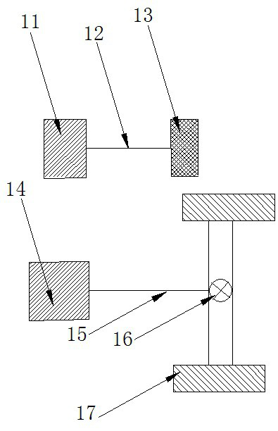
[0115] The main difference from Embodiment 1 is that in Embodiment 1, the two output shafts of the working motor are arranged coaxially, so that the driving clutch and the working clutch are correspondingly arranged on both sides of the working motor in the axial direction. In this embodiment, the two output shafts of the working motor are arranged vertically, and at this time, the positions of the driving clutch and the working clutch are also adjusted accordingly.


PUM


Abstract

The invention relates to an electric drive axle system and a pure electric operation vehicle using the system.The electric drive axle system comprises an axle, the axle comprises an axle main speed reducer, and the electric drive axle system further comprises a drive motor, an operation motor, a drive clutch and an operation clutch, the driving clutch is fixedly mounted on the driving motor, the operation motor is fixedly connected with the driving clutch, and the operation clutch is fixedly connected with the operation motor, so that the driving motor, the operation motor, the driving clutch and the operation clutch are integrally mounted on the axle, and the whole system is compact in layout; and traditional parts such as a transmission shaft and a motor suspension in an existing scheme are omitted, so that the overall cost is effectively reduced. Moreover, the power coupling of the two motors can be realized by utilizing the driving clutch, so that the vehicle can be driven to run together, the power requirement on the motors is reduced, the motors can work in a high-efficiency area, the transmission efficiency is improved, and the power consumption is reduced.

Description

technical field [0001] The invention relates to an electric drive axle system and a pure electric working vehicle using the system. Background technique [0002] The working conditions of pure electric work vehicles such as pure electric sanitation vehicles mainly include: 1. Simple road driving conditions; 2. Working conditions while driving; 3. Static working conditions to adapt to different actual needs. [0003] According to the working condition requirements of pure electric work vehicles, the distribution and arrangement of the work system and drive system are as follows: figure 1 As shown, the operation system consists of an operation motor 11 , an operation transmission shaft 12 and an operation device 13 , and the drive system consists of a drive motor 14 , a drive transmission shaft 15 , an axle differential 16 and wheels 17 . The working motor 11 drives the working device 13 to work through the working transmission shaft 12 to realize independent work. The drivi...

Claims


Application Information

Patent Timeline
IPC IPC(8): B60B35/00B60K1/02B60K17/02
CPCB60B35/00B60K1/02B60K17/02Y02T10/86
Inventor 张晓伟王慧忠徐贤亚
Owner ZHENGZHOU YUTONG BUS CO LTD
Why Eureka
Try Eureka