Gas extraction method through CO2 directional blasting crack initiation and hydrofracture coupling permeability increase

A technology of hydraulic fracturing and gas drainage, which is applied in the direction of gas discharge, mining equipment, mining fluid, etc. It can solve the problems of unfavorable gas drainage efficiency, single release pipe of fracturing equipment, and can not be adjusted, so as to improve the impact of anti-reflection range, anti-reflection cracks are uniform, and the effect of reducing the amount of work

Active Publication Date: 2017-01-04
CHONGQING UNIV
View PDF12 Cites 20 Cited by
  • Summary
  • Abstract
  • Description
  • Claims
  • Application Information

AI Technical Summary

Problems solved by technology

The patent application documents with the application numbers "201510425633.1" and "201510668034.2" disclosed the relatively advanced liquid carbon dioxide phase change fracturing antireflection methods in China, but they are all single carbon dioxide phase change fracturing antireflection methods, and the scope of the antireflection effect is small. The efficiency of gas drainage still needs to be improved; and the problem of directional fracturing is not considered. The device used cannot adjust the azimuth angle, and cannot perform directional fracturing according to the magnitude and direction of three-dimensional ground stress; In addition, it is impossible to seal the holes, which affects the fracturing effect to a certain extent and is not conducive to the further improvement of gas drainage efficiency.

Method used


Image

  • Gas extraction method through CO2 directional blasting crack initiation and hydrofracture coupling permeability increase
  • Gas extraction method through CO2 directional blasting crack initiation and hydrofracture coupling permeability increase
  • Gas extraction method through CO2 directional blasting crack initiation and hydrofracture coupling permeability increase

Examples


Embodiment Construction

[0056] Embodiments of the present invention are described in detail below, examples of which are shown in the drawings, wherein the same or similar reference numerals represent the same or similar elements or elements having the same or similar functions throughout. The embodiments described below by referring to the figures are exemplary for the purpose of explaining the present invention and should not be construed as limiting the present invention. The technical solutions and beneficial effects of the present invention will be clearer and more definite by further describing the specific embodiments of the present invention in conjunction with the accompanying drawings.

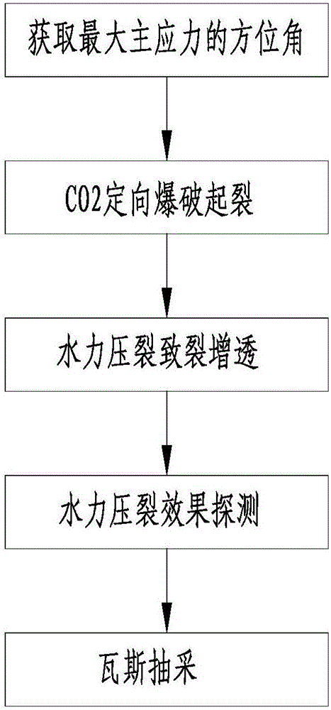
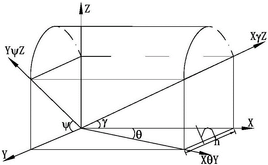
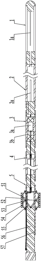
[0057] Such as figure 1 , figure 2 , image 3 with Figure 4 As shown, the present invention includes a CO 2 A gas drainage method coupled with directional blasting initiation and hydraulic fracturing for antireflection, including the following steps:

[0058] Step 1. Obtain the azimuth angle of the m...


PUM


Abstract

The invention discloses a gas extraction method through CO2 directional blasting crack initiation and hydrofracture coupling permeability increase. The maximum main stress direction of a preset fracturing point is calculated first; then in the maximum main stress direction, CO2 blasting fracturing is conducted on the fracturing point to form a fracturing hole; afterwards, hydrofracture fracturing permeability increase is conducted on the fracturing hole, the effect of hydrofracture is detected to obtain the hydrofracture influence range; and finally, coal bed gas extraction is conducted within the hydrofracture influence range. Therefore, CO2 is released in the maximum main stress direction, and the influence range of a CO2 phase change blasting fracturing crack is widened significantly. Compared with a single CO2 directional blasting fracturing permeability increase method, the permeability increase influence range is widened significantly. Compared with a single hydrofracture permeability increase method, the permeability increase cracks are more uniform. In addition, after the hydrofracture influence range is detected, drill holes are arranged reasonably for gas extraction, work amount of gas extraction drilling and fracturing holes is reduced effectively, and the cost of gas extraction is reduced.

Description

technical field [0001] The present invention relates to a CO 2 The gas drainage method of directional blasting initiation and hydraulic fracturing coupled with anti-permeability is mainly used for anti-permeability gas drainage of coal seams. Background technique [0002] At present, mine gas is the main factor affecting the safe production of coal mines in my country. Among the coal mine accidents that cause death in China, gas accidents account for a large proportion, especially serious accidents. At the same time, coalbed methane is a potential clean energy source. Under the current energy shortage situation, accelerating the development and utilization of coalbed methane has important practical significance for improving my country's energy structure, fully utilizing energy and reducing environmental pollution. Studies have shown that more than 50% of coal seams in my country are high-gas coal seams, and the geological resources of shallow coalbed methane buried below 2...

Claims


Application Information

Patent Timeline
Patent Type & Authority Applications(China)
IPC IPC(8): E21F7/00E21B43/26
CPCE21B43/006E21B43/26E21B43/261E21F7/00
Inventor 张东明白鑫尹光志王浩祖钒莹张先萌郑彬彬樊增瑞杨瀚周斌
Owner CHONGQING UNIV
Why Eureka
Try Eureka