A condenser vacuum pumping device
A technology for vacuuming equipment and condensers, applied in lighting and heating equipment, steam/steam condensers, etc., can solve problems such as increased plant power consumption, reduce losses, improve stability, and reduce power consumption Effect
- Summary
- Abstract
- Description
- Claims
- Application Information
AI Technical Summary
Problems solved by technology
Method used
Image
Examples
Embodiment 1
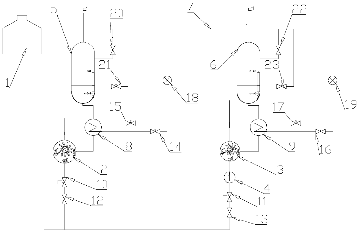
[0034] Such as figure 1 As shown, in this embodiment, a condenser vacuum pumping equipment is introduced. The air pumping port of the condenser 1 is connected to the first pipeline and the second pipeline in parallel with the first vacuum pump 2 and the second vacuum pump 3 respectively. Connection, the first pipeline and the second pipeline are respectively equipped with a control device for controlling the on-off of the pipeline; the power of the first vacuum pump 2 is greater than that of the second vacuum pump 3, and the second pipeline is equipped with a device to increase the pressure of the medium flowing into the second vacuum pump 3 The supercharging device is arranged in the upstream pipeline of the second vacuum pump 3 .
[0035]In this embodiment, the boosting device is a Roots pump 4 , and the Roots pump 4 is arranged on the second pipeline upstream of the second vacuum pump 3 . The Roots pump 4 pressurizes the gas-liquid mixed medium flowing through, so that the...
Embodiment 2
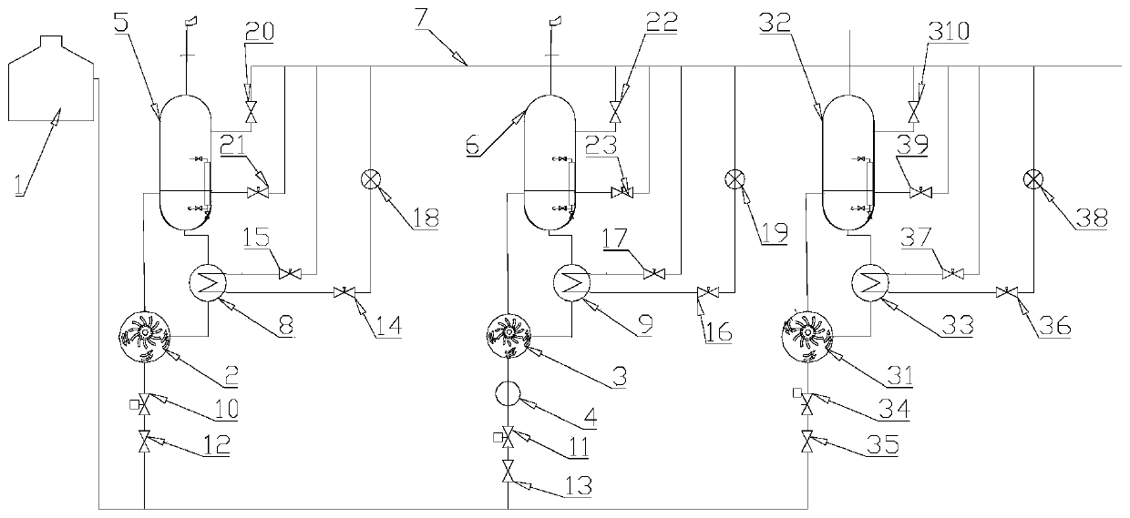
[0057] The difference between this embodiment and the above-mentioned first embodiment is that the air extraction port of the condenser 1 is connected with the third vacuum pump 31 through the third pipeline, and the third vacuum pump 31 is connected with the third steam-water separator 32 and the third cooler 33. The power of the third vacuum pump 31 is set equal to that of the first vacuum pump 2 in a circular connection.
[0058] By setting the third pipeline in parallel with the first pipeline and the second pipeline, and setting the third vacuum pump on the third pipeline, it can provide a spare vacuum branch for the condenser vacuum equipment, so as to further improve the whole machine The stability of the first vacuum pump and the second vacuum pump can be prevented from being damaged and unable to start; at the same time, when the power required for the initial stage of vacuuming is large, the first vacuum pump and the third vacuum pump can be started at the same time t...
Embodiment 3
[0067] The difference between this embodiment and the above-mentioned embodiments is that the pressurization device provided on the second pipeline is a plurality of Roots pumps 4 provided on the upstream pipeline of the second vacuum pump 3 .
[0068] In this embodiment, each Roots pump 4 is serially connected in series on the second pipeline upstream of the second vacuum pump 3 . The Roots pump 4 sequentially pressurizes the gas-liquid mixed medium flowing through, so that the pressure of the medium flowing into the second vacuum pump 3 is further increased, so as to improve the separation efficiency of the second vacuum pump, and realize the use of a low-power vacuum pump to reduce the condensed steam. The purpose of vacuumizing the condenser is to achieve the effect of reducing the overall power consumption of the condenser vacuuming equipment. At the same time, during the pressurization process, according to the working state of the second vacuum pump, one or more or all ...
PUM
 Abstract
Description
Claims
Application Information
 - R&D
- Intellectual Property
- Life Sciences
- Materials
- Tech Scout
- Unparalleled Data Quality
- Higher Quality Content
- 60% Fewer Hallucinations
Browse by: Latest US Patents, China's latest patents, Technical Efficacy Thesaurus, Application Domain, Technology Topic, Popular Technical Reports.
© 2025 PatSnap. All rights reserved.Legal|Privacy policy|Modern Slavery Act Transparency Statement|Sitemap|About US| Contact US: help@patsnap.com


