Non-scaling plate-shell type heat exchanger

A heat exchanger, plate and shell technology, applied in the field of plate and shell heat exchangers, non-fouling plate and shell heat exchangers, can solve the problems of restricting the development of new technologies, destroying water circulation, and increasing the maintenance of heat exchange equipment , to achieve thorough and efficient anti-scaling and descaling effects, eliminate problems and adverse effects, and advanced anti-scaling and descaling principles

Active Publication Date: 2017-01-04
上海兴全电力技术有限公司
View PDF11 Cites 5 Cited by
  • Summary
  • Abstract
  • Description
  • Claims
  • Application Information

AI Technical Summary

Problems solved by technology

[0011] The harm and adverse consequences caused by heat exchanger fouling include: increased investment costs; increased energy consumption; increased maintenance and cleaning costs; reduced product output and quality; increased pollut...

Method used


Image

  • Non-scaling plate-shell type heat exchanger
  • Non-scaling plate-shell type heat exchanger
  • Non-scaling plate-shell type heat exchanger

Examples


Embodiment 1

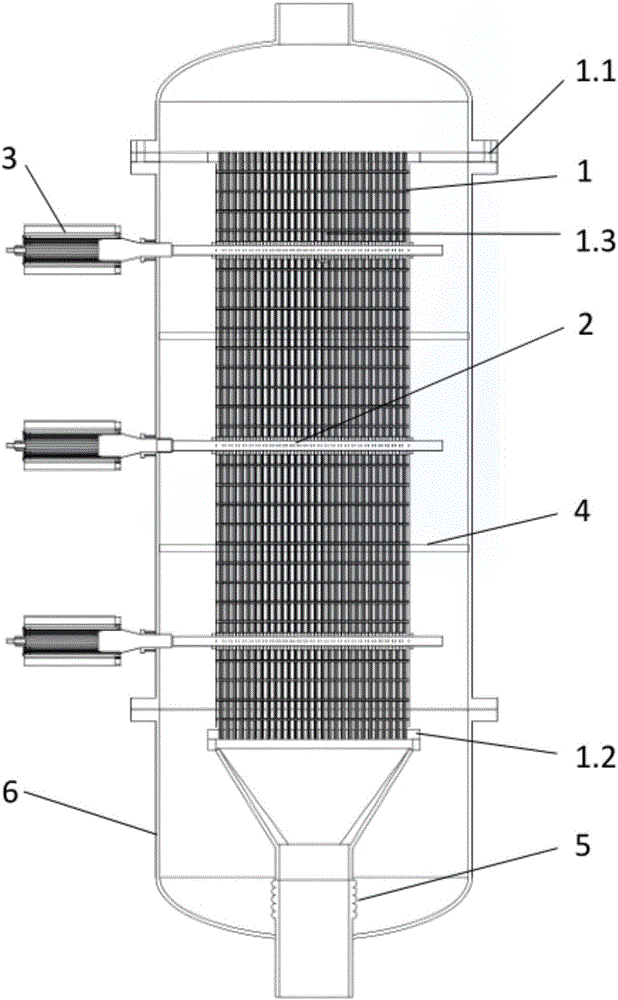
[0079] see figure 1 , the present invention discloses a non-fouling plate and shell heat exchanger. The non-fouling plate and shell heat exchanger includes: heat exchange plate group 1, at least one longitudinal power ultrasonic transmission system 2, at least one power energy wave Generator 3, at least one diversion plate 4, expansion joint 5, housing 6;

[0080] The heat exchange plate group 1, each longitudinal power ultrasonic transmission system 2, and each flow guide partition 4 are arranged in the housing, and the power energy wave generator 3 is connected to the corresponding longitudinal power ultrasonic transmission system 2; the inside of the heat exchanger and the tube plate The expansion joint 5 is arranged between them.

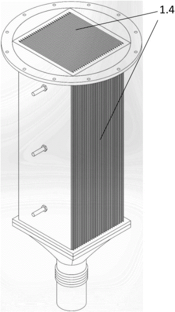
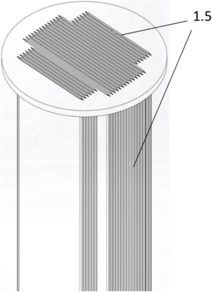
[0081] The heat exchange plate group 1 includes: an upper tube plate 1.1, a lower tube plate 1.2, and a heat transfer fin 1.3; the heat transfer fin 1.3, the upper tube plate 1.1, and the lower tube plate 1.2 must be well welded.

[0082] Such...

Embodiment 2

[0097] A non-fouling plate and shell heat exchanger, the non-fouling plate and shell heat exchanger includes: heat exchange plate group, at least one longitudinal power ultrasonic transmission system, at least one power energy wave generator, at least one guide Partition, shell;

[0098] The heat exchange plate group, each longitudinal power ultrasonic transmission system, and each deflector partition are arranged in the shell, and the power energy wave generator is connected to the corresponding longitudinal power ultrasonic transmission system; expansion joint.

[0099] In summary, the non-fouling plate and shell heat exchanger proposed by the present invention not only has the characteristics of high heat exchange efficiency and small footprint of the plate heat exchanger; it also has the high temperature and high pressure resistance of the shell and tube heat exchanger. Features, and the enhanced heat transfer effect is remarkable, representing the development direction o...


PUM


Abstract

The invention discloses a non-scaling plate-shell type heat exchanger. The non-scaling plate-shell type heat exchanger comprises a heat exchanging plate group, at least one longitudinal power ultrasonic transmission system, at least one power energy wave generator, at least one deflector partition plate and a shell, wherein the heat exchanging plate group, the longitudinal power ultrasonic transmission system and the deflector partition plate are arranged in the shell, and the power energy wave generator is connected with the corresponding longitudinal power ultrasonic transmission system; and an expansion node is arranged between the interior of the heat exchanger and a tube plate. The non-scaling plate-shell type heat exchanger not only has the characteristics that the plate type heat exchanger is high in heat exchange efficiency and small in occupation area, but also has the characteristics that the shell type heat exchange resists high temperature and high pressure, the enhanced heat exchange effect is obvious, and the non-scaling plate-shell type heat exchanger represents the development direction of high-efficiency and energy-saving heat exchange products.

Description

technical field [0001] The invention belongs to the technical field of heat exchangers, and relates to a plate and shell heat exchanger, in particular to a non-fouling plate and shell heat exchanger. Background technique [0002] Fouling is a layer of solid matter that develops on heat transfer surfaces in contact with unclean fluids. Fouling exists in many fields of the process industry, and the fouling of the heating surface and the heat transfer surface has become one of the main problems that plague the normal operation of the equipment in the heat exchange process. Fouling leads to a decline in thermal efficiency, increased heat transfer resistance, increased energy consumption, and in serious cases, blocked pipes and even caused boiler explosions and other serious consequences. Dirt has been bothering people for thousands of years, no matter in the past or now, developing countries or developed countries are suffering from it, and there is still no effective way to so...

Claims


Application Information

Patent Timeline
IPC IPC(8): F28D9/00F28F3/08F28F19/00F28F13/02
CPCF28D9/0037F28F3/08F28F13/02F28F19/00
Inventor 褚兴全吴伯刚褚校崧
Owner 上海兴全电力技术有限公司
Why Eureka
Try Eureka