
Attached unsteady cavitation flow internal shock wave structure capturing apparatus and capturing method

A capture device and unsteady technology, applied in the fields of ship and underwater vehicle engineering, water conservancy and hydropower engineering, and can solve problems such as the inability to accurately capture the structure of cavitation fluid shock waves

Active Publication Date: 2017-01-04
BEIJING INSTITUTE OF TECHNOLOGYGY
View PDF8 Cites 15 Cited by
  • Summary
  • Abstract
  • Description
  • Claims
  • Application Information

AI Technical Summary

Problems solved by technology

[0004] The purpose of the present invention is: to provide a kind of phase distribution field (cavitation form), velocity field (velocity measurement), pressure field (wall surface pressure measurement) and internal structure of cavitation fluid (shock wave structure) of unsteady cavitation flow to be acquired synchronously ) device and method to solve the problem that the existing measuring equipment cannot accurately capture the shock wave structure inside the cavitation fluid

Method used


Image

  • Attached unsteady cavitation flow internal shock wave structure capturing apparatus and capturing method
  • Attached unsteady cavitation flow internal shock wave structure capturing apparatus and capturing method
  • Attached unsteady cavitation flow internal shock wave structure capturing apparatus and capturing method

Examples


Embodiment 1

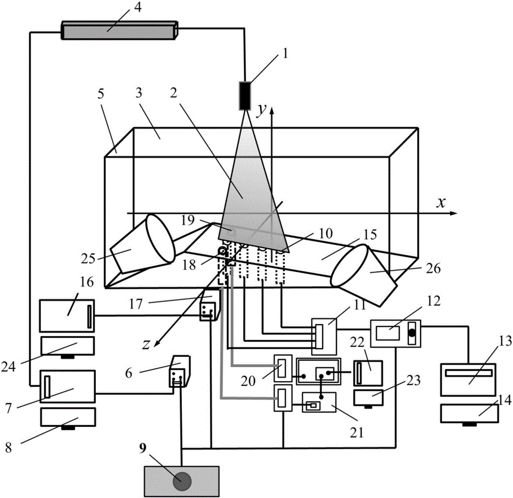
[0023] Embodiment 1, referring to the accompanying drawings, an attached type unsteady cavitation fluid internal shock wave structure capture device, which includes: an experimental platform, a high-speed full flow field display subsystem, an endoscope display subsystem, a particle image velocimetry subsystem, a pressure Measurement subsystem and synchronous trigger subsystem;

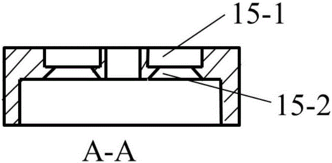
[0024] The experimental platform includes: a test section 5 for the attached cavitation fluid to flow through in the closed circulating water tunnel, an experimental model 15 arranged in the test section 5, and a transparent organic glass 3 for observation surrounding the top, bottom and sides of the test section 5;

[0025] The high-speed full flow field display subsystem includes: the first high-speed camera 17 for shooting the full flow field of the test section 5, the dysprosium lamps 25 and 26 that provide illumination for the first high-speed camera 17 to shoot, and record and display the first hi...

Embodiment 2

[0032] Embodiment 2, see attached Figure 4 The attached type unsteady cavitation fluid internal shock wave structure capture method, which uses the attached type unsteady cavitation fluid internal shock wave structure capture device as described in embodiment 11, and includes the following steps:

[0033] A. Adjust the flow parameters to generate cavitation flow in the test section in the closed circulation water tunnel;

[0034] B. Start the high-speed full flow field display subsystem, the endoscope display subsystem, the particle image velocimetry subsystem and the pressure measurement subsystem respectively, set the first high-speed camera 17, the second high-speed camera 6, the CCD camera 20, the particle image Acquisition frequency and acquisition time length of velocimetry and pressure measurement; make the high-speed full flow field display subsystem, endoscope display subsystem, particle image velocimetry subsystem and pressure measurement subsystem wait for triggeri...


PUM


Abstract

The invention belongs to the technical field of ship and underwater navigation device engineering and water resources and hydropower engineering, and in particular to the technology of attached cavitation flow experiments. The attached unsteady cavitation flow internal shock wave structure capturing apparatus includes an experiment platform, a high-speed whole flow field display sub-system, an endoscope display sub-system, a particle image speed measuring sub-system, a pressure measuring sub-system and a synchronous triggering sub-system. According to the invention, the capturing apparatus can be in combination with a plurality of experiment measuring devices, synchronously observe and measure cavitation flows, and conduct comprehensive research on the internal complex shock wave structure coupled by multi-fields of the attached unsteady cavitation flows.

Description

technical field [0001] The invention belongs to the technical fields of ship and underwater vehicle engineering and water conservancy and hydropower engineering, and in particular relates to an attached cavitation fluid experiment technology. Background technique [0002] Adhesive cavitation fluid flow involves almost all complex flow phenomena such as turbulence, momentum and mass exchange, compressibility and unsteadiness, which makes the internal structure of adherent unsteady cavitation fluid very complicated. With the increase of the gas content in the attached cavitation fluid, the sound velocity of the cavitation fluid will decrease significantly, which will lead to the generation of shock wave structure under certain working conditions. mechanism research. The difficulty of this work lies in the capture and observation of the shock wave structure. Therefore, it is urgent to invent new research methods to carry out this work. [0003] Due to the complexity of cavita...

Claims


Application Information

Patent Timeline
IPC IPC(8): G01M10/00
CPCG01M10/00
Inventor 王国玉王畅畅黄彪张敏弟高德明
Owner BEIJING INSTITUTE OF TECHNOLOGYGY
Learn More