A high-vacuum adiabatic visualized thermoacoustic nuclear element and thermoacoustic system
A thermoacoustic system, high vacuum technology, applied in the fields of thermodynamics, fluid mechanics and acoustics, thermoacoustic heat engine, to achieve the effect of reducing radiation heat leakage
- Summary
- Abstract
- Description
- Claims
- Application Information
AI Technical Summary
Problems solved by technology
Method used
Image

Examples
Embodiment 1
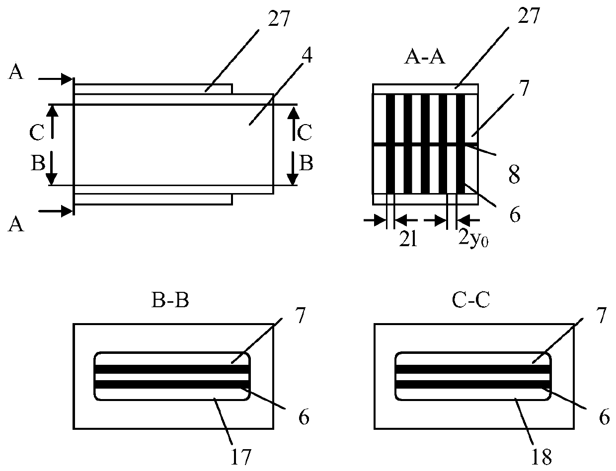
[0039] figure 1 Shown is a schematic diagram of a specific embodiment of the thermoacoustic nuclear element 4 in the present invention. Such as figure 1 As shown, the thermoacoustic nuclear element 4 is a cuboid in which a gas working medium circulates inside; a hot end heat exchanger 10, a parallel plate stack 6 and a cold end heat exchanger 9 are arranged inside from left to right; Between the hot end heat exchanger 10, the parallel plate stack 6 and the flat plate of the cold end heat exchanger 9 is an air passage space 7, and the tracer particles 5 are filled in the air passage space 7; the upper end of the thermoacoustic nuclear element 4 The cover is a transparent viewing window, and a zinc sulfide crystal 18 is installed in the window, and the lower end cover of the thermoacoustic nuclear element 4 is a transparent viewing window, and quartz glass 17 is installed in the window; an adiabatic cover 27 is arranged outside the thermoacoustic nuclear element 4, The upper e...
Embodiment 2
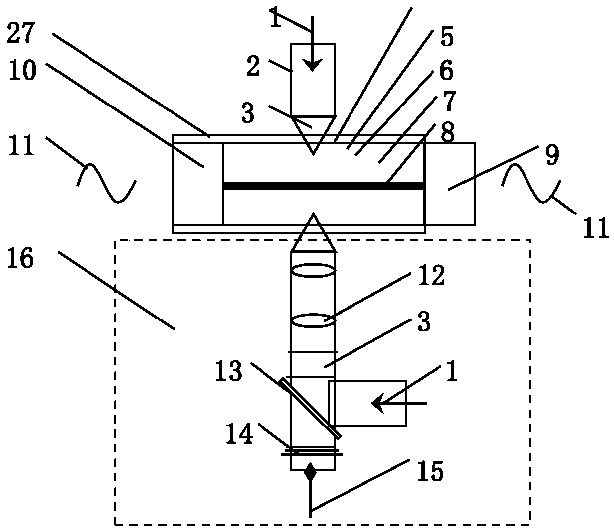
[0044] Such as figure 2 It shows that for the measurement of the thermal field and sound field in the thermoacoustic mesoscopic test system, in the thermoacoustic system, its core component is the thermoacoustic nuclear element 4. According to the different principles of the thermoacoustic engine and the thermoacoustic refrigerator, the , self-excited oscillations can occur to generate sound waves 11; in a thermoacoustic refrigerator, sound waves 11 are input to the hot-end heat exchanger 10 from sound-generating components such as speakers. The thermoacoustic system includes: a thermoacoustic nuclear element 4, an infrared thermal imager 2 and a particle imaging velocimeter 16; the infrared thermal imager 2 is arranged on the upper end of the thermoacoustic nuclear element 4, and the particle imaging velocimeter 16 is arranged At the lower end of the thermoacoustic nuclear element 4, a light baffle 8 is vertically arranged in the middle of the parallel plate stack 6 of the t...
Embodiment 3
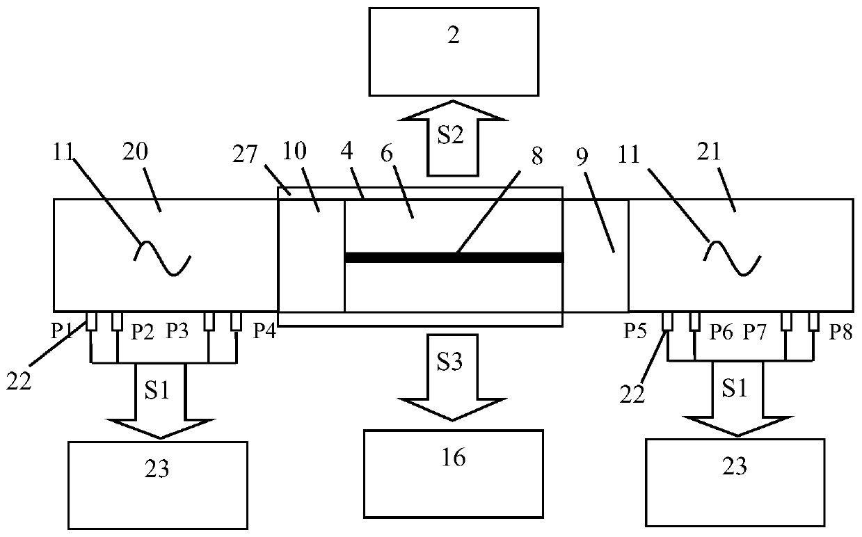
[0047] image 3 It is a schematic diagram of an embodiment of the present invention applied to a standing wave thermoacoustic engine. The shown thermoacoustic engine comprises a left resonant pipe section 20 , a thermoacoustic nuclear element 4 and a right resonant pipe section 21 . The working mechanism of the thermoacoustic engine is to establish a temperature gradient at both ends of the parallel plate stack 6. When the temperature gradient reaches the critical temperature gradient of the thermoacoustic system, self-excited oscillation is generated in the engine to output sound power. Such as image 3 As shown, the high temperature and low temperature at both ends of the parallel plate stack 6 are controlled at a constant value by means of heating at the side of the heat exchanger 10 at the hot end and cooling with circulating water at the side of the heat exchanger 9 at the cold end. On the resonant pipe section 20 on the side of the heat exchanger 10 at the hot end, the...
PUM
 Abstract
Description
Claims
Application Information
 - R&D
- Intellectual Property
- Life Sciences
- Materials
- Tech Scout
- Unparalleled Data Quality
- Higher Quality Content
- 60% Fewer Hallucinations
Browse by: Latest US Patents, China's latest patents, Technical Efficacy Thesaurus, Application Domain, Technology Topic, Popular Technical Reports.
© 2025 PatSnap. All rights reserved.Legal|Privacy policy|Modern Slavery Act Transparency Statement|Sitemap|About US| Contact US: help@patsnap.com