
High-vacuum heat insulation visual thermo-acoustic core element and thermo-acoustic system

A thermoacoustic system, high vacuum technology, applied in indirect heat exchangers, refrigeration and liquefaction, heat exchanger types, etc., to achieve the effect of reducing radiation heat leakage

Active Publication Date: 2019-02-05
TECHNICAL INST OF PHYSICS & CHEMISTRY - CHINESE ACAD OF SCI
View PDF7 Cites 1 Cited by
  • Summary
  • Abstract
  • Description
  • Claims
  • Application Information

AI Technical Summary

Problems solved by technology

[0005] The purpose of the present invention is to overcome the heat leakage problem existing in the current thermoacoustic nucleus, and provide a visual thermoacoustic nuclear element with high vacuum insulation and a real thermoacoustic system that can be applied to thermoacoustic mesoscopic testing

Method used


Image

  • High-vacuum heat insulation visual thermo-acoustic core element and thermo-acoustic system
  • High-vacuum heat insulation visual thermo-acoustic core element and thermo-acoustic system
  • High-vacuum heat insulation visual thermo-acoustic core element and thermo-acoustic system

Examples


Embodiment 1

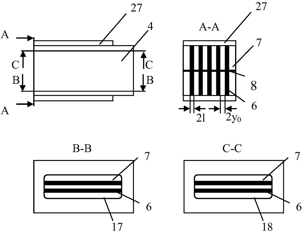
[0039] figure 1 Shown is a schematic diagram of a specific embodiment of the thermoacoustic nuclear element 4 in the present invention. Such as figure 1 As shown, the thermoacoustic nuclear element 4 is a cuboid in which a gas working medium circulates inside; a hot end heat exchanger 10, a parallel plate stack 6 and a cold end heat exchanger 9 are arranged inside from left to right; Between the hot end heat exchanger 10, the parallel plate stack 6 and the flat plate of the cold end heat exchanger 9 is an air passage space 7, and the tracer particles 5 are filled in the air passage space 7; the upper end of the thermoacoustic nuclear element 4 The cover is a transparent viewing window, and a zinc sulfide crystal 18 is installed in the window, and the lower end cover of the thermoacoustic nuclear element 4 is a transparent viewing window, and quartz glass 17 is installed in the window; an adiabatic cover 27 is arranged outside the thermoacoustic nuclear element 4, The upper e...

Embodiment 2

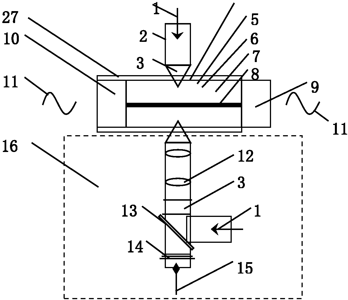
[0044] Such as figure 2 It shows that for the measurement of the thermal field and sound field in the thermoacoustic mesoscopic test system, in the thermoacoustic system, its core component is the thermoacoustic nuclear element 4. According to the different principles of the thermoacoustic engine and the thermoacoustic refrigerator, the , self-excited oscillations can occur to generate sound waves 11; in a thermoacoustic refrigerator, sound waves 11 are input to the hot-end heat exchanger 10 from sound-generating components such as speakers. The thermoacoustic system includes: a thermoacoustic nuclear element 4, an infrared thermal imager 2 and a particle imaging velocimeter 16; the infrared thermal imager 2 is arranged on the upper end of the thermoacoustic nuclear element 4, and the particle imaging velocimeter 16 is arranged At the lower end of the thermoacoustic nuclear element 4, a light baffle 8 is vertically arranged in the middle of the parallel plate stack 6 of the t...

Embodiment 3

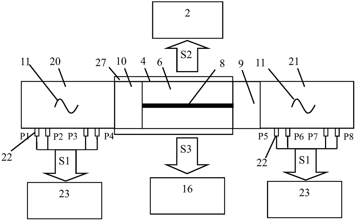
[0047] image 3 It is a schematic diagram of an embodiment of the present invention applied to a standing wave thermoacoustic engine. The shown thermoacoustic engine comprises a left resonant pipe section 20 , a thermoacoustic nuclear element 4 and a right resonant pipe section 21 . The working mechanism of the thermoacoustic engine is to establish a temperature gradient at both ends of the parallel plate stack 6. When the temperature gradient reaches the critical temperature gradient of the thermoacoustic system, self-excited oscillation is generated in the engine to output sound power. Such as image 3 As shown, the high temperature and low temperature at both ends of the parallel plate stack 6 are controlled at a constant value by means of heating at the side of the heat exchanger 10 at the hot end and cooling with circulating water at the side of the heat exchanger 9 at the cold end. On the resonant pipe section 20 on the side of the heat exchanger 10 at the hot end, the...


PUM


Abstract

The invention discloses a high-vacuum heat insulation visual thermo-acoustic core element. The heat-acoustic core element (4) is a cuboid with a gas working medium circulating inside; a hot-end heat exchanger (10), a parallel type plate stack (6) and a cold-end heat exchanger (9) are arranged inside the heat-acoustic core element from left to right; gas channel space (7) is arranged among flat plates among the hot-end heat exchanger (10), the parallel type plate stack (6) and the cold-end heat exchanger (9), and the gas channel space (7) is filled with tracing particles (5); the upper end cover of the heat-acoustic core element (4) is a transparent visual window, a zinc sulfide crystal (18) is installed in the window, the lower end cover of the heat-acoustic core element (4) is a transparent visual window, and quartz glass (17) is installed in the window; and a heat insulation cover (27) is arranged outside the heat-acoustic core element (4), the upper end cover of the heat insulationcover (27) is a transparent visual window, the zinc sulfide crystal (18) is installed in the window, the lower end cover of the heat insulation cover (27) is a transparent visual window, and the quartz glass (17) is installed in the window.

Description

technical field [0001] The invention mainly relates to the fields of thermoacoustic heat engine, thermodynamics, fluid mechanics and acoustics, and particularly relates to a high-vacuum adiabatic visualized thermoacoustic nuclear element and a thermoacoustic system. Background technique [0002] The thermoacoustic heat engine is a new type of high-efficiency heat engine. It uses the thermoacoustic phenomenon in physics to make the working gas complete the thermodynamic microcirculation at the mesoscopic level in the microstructure channel of the plate stack (regenerator), and directly realize the thermal energy to the acoustic energy. able to convert each other. The plate stack (regenerator) is the core element in the thermoacoustic heat engine to realize the conversion of heat energy (sound energy) to sound energy (thermal energy), and is the thermodynamic second medium in the thermoacoustic process. The element is called a plate stack in a standing wave thermoacoustic hea...

Claims


Application Information

Patent Timeline
Patent Type & Authority Applications(China)
IPC IPC(8): F28D9/00F25B23/00F02G1/043
CPCF02G1/043F02G2243/54F25B23/00F28D9/00
Inventor 谢秀娟杨少柒刘丰豪
Owner TECHNICAL INST OF PHYSICS & CHEMISTRY - CHINESE ACAD OF SCI
Learn More