
A DC high voltage measurement and correction system and method based on DC voltage divider time-division sampling

A technology of DC voltage divider and time-sharing sampling, which is applied in the direction of measuring current/voltage, only measuring voltage, measuring devices, etc. It can solve the problem that it is difficult to improve the measurement accuracy technology, the cost performance is not high, and the DC voltage divider Accuracy impact and other issues, to achieve the effect of measurement and correction

Active Publication Date: 2019-02-05
XI AN JIAOTONG UNIV
View PDF9 Cites 0 Cited by
  • Summary
  • Abstract
  • Description
  • Claims
  • Application Information

AI Technical Summary

Problems solved by technology

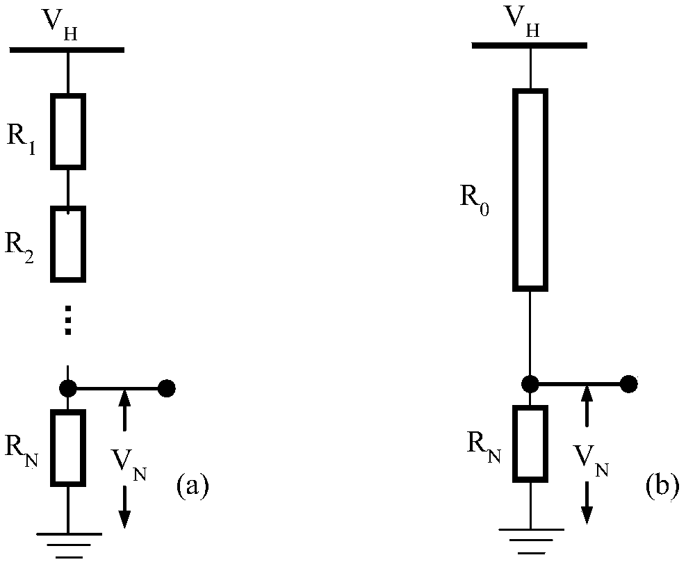
However, due to the influence of the voltage dispersion and aging trend of the resistance components, the influence of the corona discharge of the high-voltage arm and the influence of the insulation leakage of the voltage divider under high voltage conditions, this method is also easily affected by external environmental factors. , including ambient temperature, dirt on the surface of the DC voltage divider, objects near the DC voltage divider, etc., will affect the accuracy of the DC voltage divider and often need to be calibrated
[0010] In summary, although the above-mentioned DC high-voltage measurement methods have been widely used in the field of electrical engineering, instrument science and technology, it is difficult to improve the measurement accuracy in terms of technology, or to improve the measurement accuracy. Accuracy yields poor price / performance ratio

Method used


Image

  • A DC high voltage measurement and correction system and method based on DC voltage divider time-division sampling
  • A DC high voltage measurement and correction system and method based on DC voltage divider time-division sampling
  • A DC high voltage measurement and correction system and method based on DC voltage divider time-division sampling

Examples


Embodiment

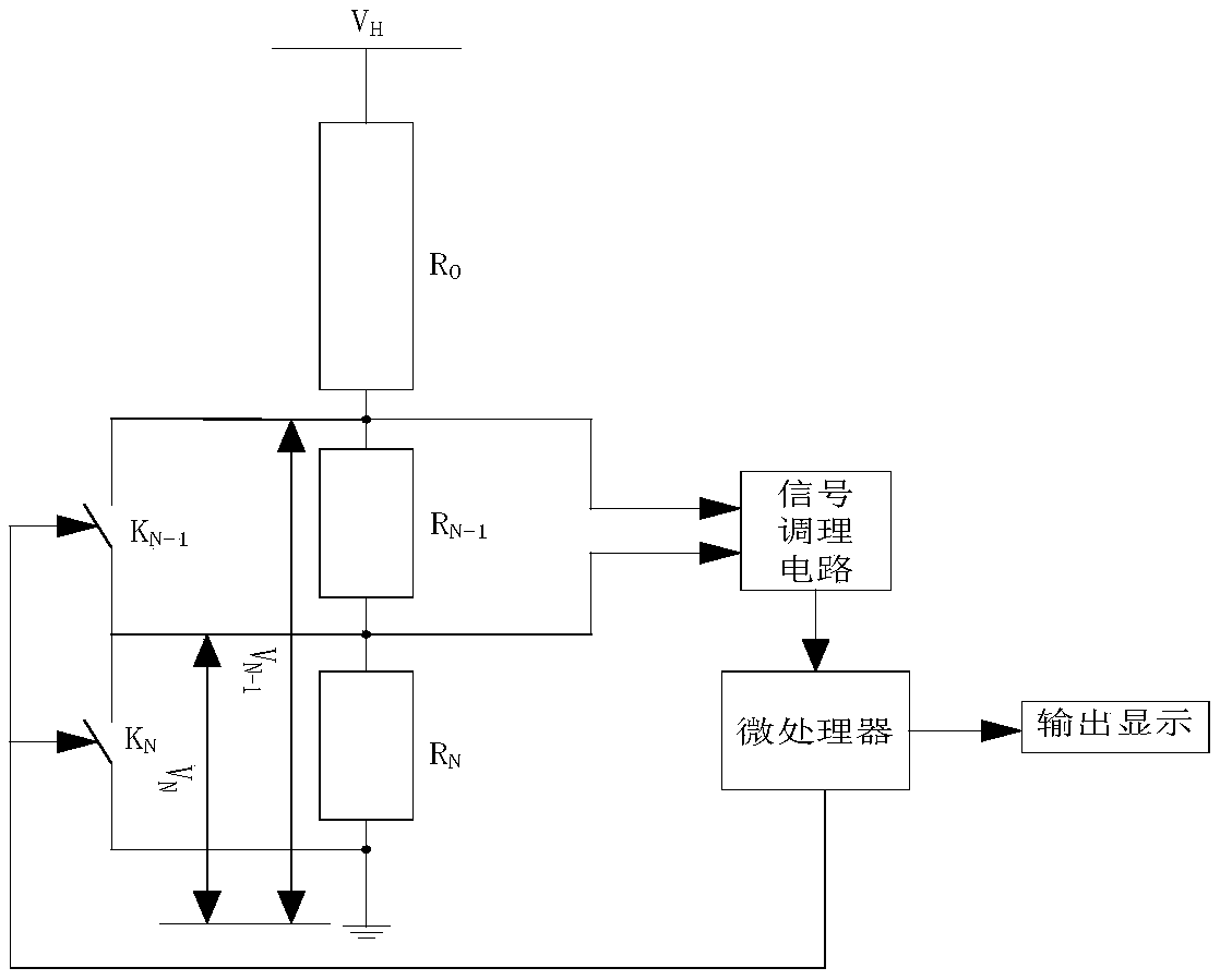
[0057] This embodiment combines image 3 A schematic diagram of the measurement system structure briefly illustrates the implementation process. Assuming that the measured DC voltage is 100kV, the system uses a MOSFET tube as a switch, which is turned on when the gate is high voltage, and the C51 single-chip microcomputer is used as a microprocessor. The quasi-bidirectional port of the single-chip microcomputer is used to control the MOSFET tube. , the resistance value of each resistor is 1MΩ, the rated power is 2W, the resistance value of the precision resistors is 50kΩ, and the accuracy level requirement of the DC voltage divider is 0.5. Therefore, at rated voltage, R N The voltage V N about 50V, R N-1 The voltage V N-1 It is about 100V, the resolution of the acquisition card is 16 bits, the voltage input range is 0-5V, and the conditioning circuit converts V N and V N-1 Regulated into 0 ~ 5V. The measurement process of the voltage divider, the realization of the inst...


PUM


Abstract

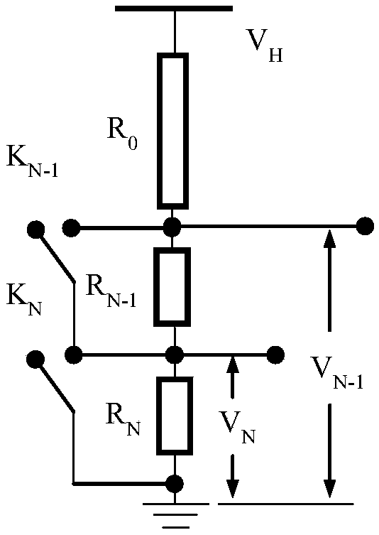
The invention discloses a direct-current high-voltage measurement and correction system and a method based on time-sharing sampling of a direct-current voltage divider. The method comprises the following steps: mounting two serially connected precise sampling resistors on a low-voltage arm side of the direct-current voltage divider; connecting two switches in parallel on the two resistors respectively; performing time-sharing data acquisition on voltage of two low-voltage resistor arms in a switching mode; establishing equations to calculate the resistance value of the high-voltage arm of the direct-current voltage divider, thereby calibrating the resistance of the high-voltage arm of the direct-current voltage divider. In real measurement, the voltage of each sampling resistor is directly measured, and the direct-current bus voltage is calculated according to voltage division principles, so that environment parameter influence of voltage divider elements and influence of variation of factors such as discharge on measurement results can be reduced, self-calibration of the direct-current voltage divider can be achieved, and the reliability and accuracy of direct-current high-voltage detection can be improved.

Description

【Technical field】 [0001] The invention relates to the fields of electrical engineering, instrument science and technology, and relates to the direction of high-voltage technology, and specifically adopts a DC high-voltage measurement and correction system and method based on time-sharing sampling of a DC voltage divider. 【Background technique】 [0002] There are three main methods for measuring DC high voltage. [0003] The first method is to realize the measurement of DC voltage by observing various physical effects produced by the direct action of DC voltage. This measurement method includes: [0004] Electrostatic voltmeter, when a voltage is applied to two opposite electrodes, since the two electrodes are charged with charges of opposite polarity, the electrodes will be affected by electrostatic force, by measuring the magnitude of the electrostatic force, or measuring the electrostatic force produced The offset of a certain plate is used to calculate the applied volta...

Claims


Application Information

Patent Timeline
Patent Type & Authority Patents(China)
IPC IPC(8): G01R19/00
CPCG01R19/0084
Inventor 汤晓君周生刘帅张峰
Owner XI AN JIAOTONG UNIV
Learn More