
Intelligent track circuit shunt parameter tester and realization method thereof

A track circuit and tester technology, which is applied in the direction of electronic circuit testing, instrumentation, and electrical measurement, and can solve problems such as simple tooling, poor test accuracy, and inconvenient operation

Inactive Publication Date: 2017-01-04
袁伟家
View PDF13 Cites 0 Cited by
  • Summary
  • Abstract
  • Description
  • Claims
  • Application Information

AI Technical Summary

Problems solved by technology

[0004] At present, there are two main problems in the test of track circuit parameters: 1. Since the rail line is exposed to the air, the surface is oxidized and corroded, so the test results are often inaccurate during the track surface test or branch test; 2. .The shunt resistance between the two rails is 0.15Ω or 0.25Ω according to the railway standard. The current shunt test tooling is simple and the resistance value error is large, which is difficult to meet the standard requirements, and the operation is inconvenient, the work efficiency is low, and the test accuracy is low. Difference

Method used


Image

  • Intelligent track circuit shunt parameter tester and realization method thereof
  • Intelligent track circuit shunt parameter tester and realization method thereof
  • Intelligent track circuit shunt parameter tester and realization method thereof

Examples


Embodiment Construction

[0032] The specific implementation manners of the present invention will be further described in detail below in conjunction with the accompanying drawings.

[0033] The following description and drawings illustrate specific embodiments of the invention sufficiently to enable those skilled in the art to practice them. Other embodiments may incorporate structural, logical, electrical, process, and other changes. The examples merely represent possible variations. Individual components and functions are optional unless explicitly required, and the order of operations may vary. Portions and features of some embodiments may be included in or substituted for those of other embodiments. The scope of embodiments of the present invention includes the full scope of the claims, and all available equivalents of the claims. These embodiments of the present invention may be referred to herein, individually or collectively, by the term "invention", which is for convenience only and is not...


PUM


Abstract

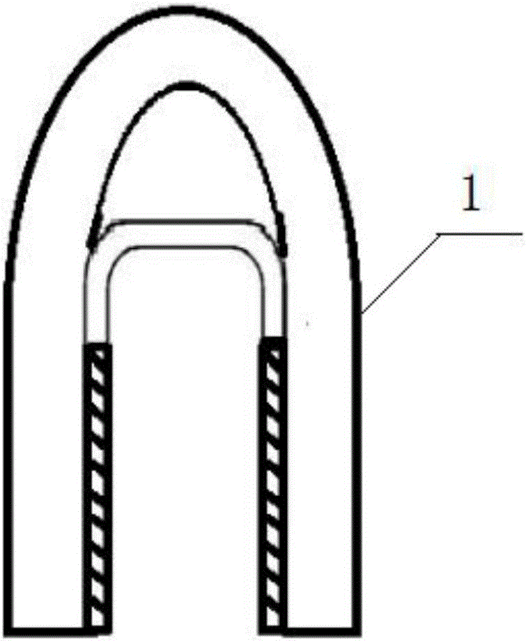
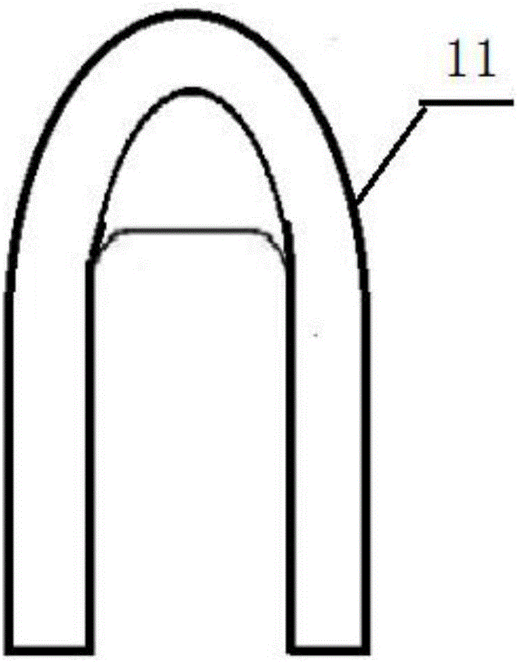
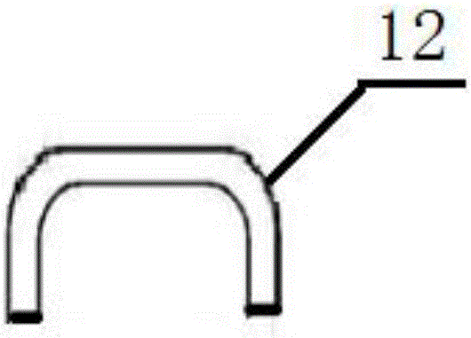
The invention relates to an intelligent track circuit shunt parameter tester and a test method thereof. The intelligent track circuit shunt parameter tester comprises a hand-held tool that matches the shape of the surfaces of steel rails and a test instrument that is connected to a contact copper board of the hand-held tool via a copper wire. The hand-held tool has three parts, namely, an integrated outer sheath with a handle, the contact copper board with the same arc shape as the surface of the steel rails and a rust-removing filing board. The copper wire is led out from the contact copper board of the hand-held tool. The instrument is arranged in a customized housing. Two copper pillars are installed at the top of the housing and are connected to the copper wire on the back of the housing. After the instrument is mounted in the housing, shunt electrical signals can be effectively obtained through the two copper pillars, and calculation is automatically carried out according to the electric signals. The technical scheme provided by the invention can solve the problem of poor contact of the tester which may be caused due to corrosion of the steel rail, and the rail surface voltage between the two steel rails and the shunt current after the two steel rails are shunted can be measured efficiently and conveniently.

Description

technical field [0001] The invention relates to a track circuit tester, in particular to an intelligent tester for track circuit branch parameters and a realization method thereof. Background technique [0002] The track circuit is a circuit composed of the track circuit system equipment and the rail line. The track circuit system equipment forms a complete circuit through the rail line, and the track circuit signal is transmitted to the train through the rail to control the train to run at different speeds on the railway line. or parking. [0003] In order to ensure that the track circuit signal can be reliably received by the train, it is very necessary to test the track circuit signal on the rail line. The track circuit signal test on the rail line mainly includes the rail surface voltage test between two rails and the shunt current test after the two rails are split. [0004] At present, there are two main problems in the test of track circuit parameters: 1. Because th...

Claims


Application Information

Patent Timeline
IPC IPC(8): G01R31/28G01R19/00G01R1/04
CPCG01R1/04G01R19/00G01R31/282
Inventor 袁伟家
Owner 袁伟家
Learn More