Lighting liquid crystal display panel and liquid crystal display device and display terminal

A liquid crystal panel and liquid crystal technology, applied in optics, nonlinear optics, instruments, etc., can solve the problems of increased thickness, high cost, and low light efficiency, and achieve the effects of easy assembly, simple structure, and uniform light distribution

Active Publication Date: 2017-01-04
宋义
View PDF8 Cites 3 Cited by
  • Summary
  • Abstract
  • Description
  • Claims
  • Application Information

AI Technical Summary

Problems solved by technology

[0004] The object of the present invention is to provide a liquid crystal panel and a liquid crystal display device, aiming to solve the problems that the traditional liquid crystal display device needs an additional supporting backlight, which leads to thicker thickness, high cost, and low light efficiency

Method used


Image

  • Lighting liquid crystal display panel and liquid crystal display device and display terminal
  • Lighting liquid crystal display panel and liquid crystal display device and display terminal
  • Lighting liquid crystal display panel and liquid crystal display device and display terminal

Examples


Embodiment Construction

[0036] In order to make the object, technical solution and advantages of the present invention clearer, the present invention will be further described in detail below in conjunction with the accompanying drawings and embodiments. It should be understood that the specific embodiments described here are only used to explain the present invention, not to limit the present invention.

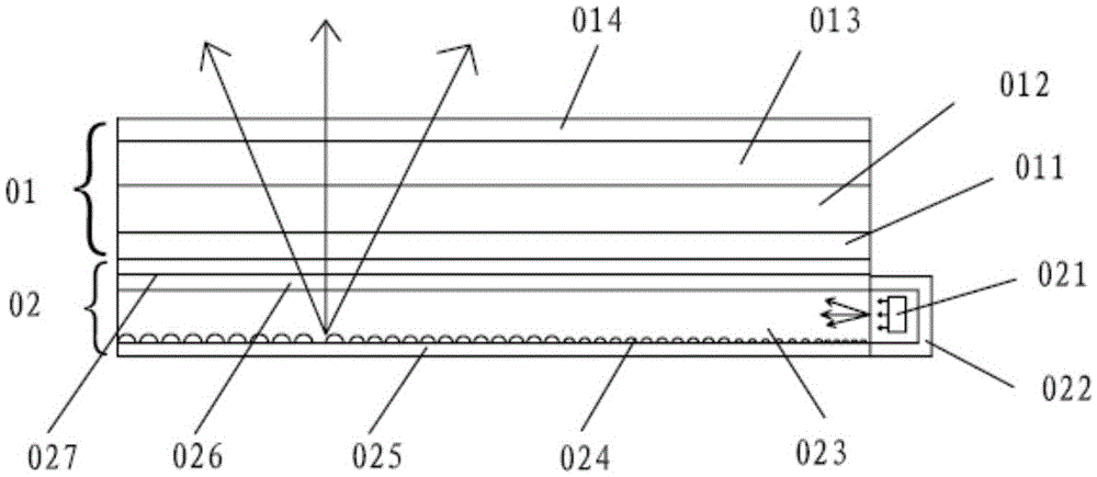
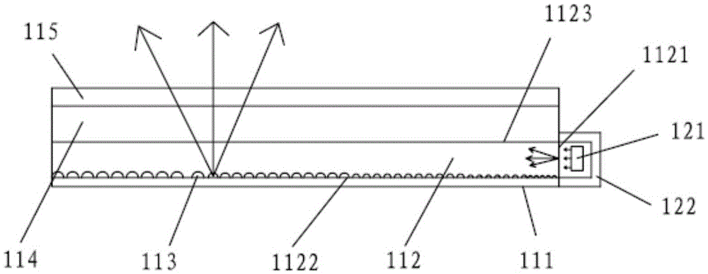
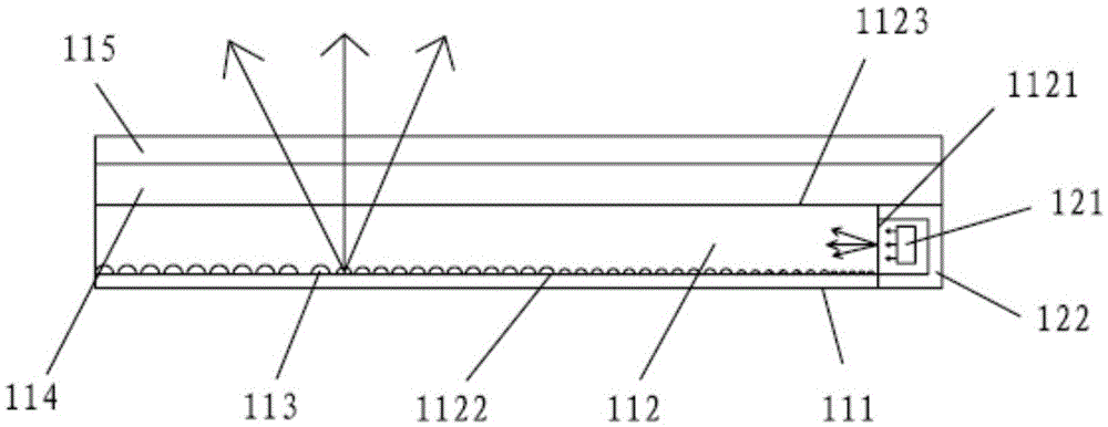
[0037] The embodiment of the present invention provides that the lower glass plate of the liquid crystal panel is processed into a light guide, and the bottom surface of the lower glass plate is processed by laser lithography, engraving, etching, photolithography, printing, electricity, physics, chemical treatment, etc. The formed micro-geometry, or one plane or more than one N planes inside the lower glass plate parallel to the bottom surface are formed by one or more processes in the micro-geometry formed by laser lithography or doping in the light guide body The micro-geometry makes the distribu...


PUM

PropertyMeasurementUnit
sizeaaaaaaaaaa

Abstract

The invention discloses a lighting liquid crystal display panel. The lighting liquid crystal display panel comprises an upper glass plate, a lower glass plate, a liquid crystal, a circuit and the like. The lower glass plate is used for achieving the light guiding function, and comprises a light inlet face, a light outlet face and a light guiding body, wherein the light inlet face is arranged on the side face of the lower glass plate and rightly opposite to light beams emitted by a light source of the light inlet face, the part of light beams directly enter the lower glass plate through the light inlet face, the other part of light beams are reflected by a reflecting cover to enter the lower glass plate through the light inlet face; the light outlet face is arranged on the upper bottom face of the lower glass plate and used for guiding out the light beams in the lower glass plate; the light guiding body is arranged on the lower bottom face of the lower glass plate or arranged inside the lower glass plate and parallel to the light outlet face; a plurality of micro geometries for reflecting or refracting the light beams are sequentially arranged on the light guiding body. By means of the lighting liquid crystal display panel, the light guiding effect of an original backlighting source can be developed through the lower glass plate, propagation media and paths of light are greatly reduced, and the using ratio of light and the light outlet efficiency of the liquid crystal display panel are improved.

Description

technical field [0001] The invention relates to the field of photoelectric display, in particular to a liquid crystal panel with simple structure and high luminous efficiency, a liquid crystal display device and a liquid crystal display terminal. Background technique [0002] With the development of flat panel display technology, the application range of liquid crystal panels and liquid crystal display devices is becoming wider and wider, such as liquid crystal TVs, liquid crystal displays, notebooks, smart phones, tablet computers, various wearable products and various application display terminals. All these application terminals require a friendly display interface, and the optical performance of the liquid crystal panel determines the display effect of the entire liquid crystal display device. [0003] Such as figure 1 As shown, the existing liquid crystal display device is generally composed of a liquid crystal panel 01 and a backlight source 02 , the liquid crystal pa...

Claims


Application Information

Patent Timeline
Patent Type & Authority Applications(China)
IPC IPC(8): G02F1/13357
CPCG02F1/133615
Inventor 宋义邹华德
Owner 宋义
Why Eureka
Try Eureka