Method for predicting ground settlement caused by soil bin soil entering and discharge through soil pressure balance shield

A technology of earth pressure balance shield tunneling and surface subsidence, applied in special data processing applications, instruments, electrical digital data processing, etc., can solve problems such as late feedback of surface subsidence information, rough surface subsidence prediction formulas, and inconsistencies

Active Publication Date: 2017-01-04
CENT SOUTH UNIV
View PDF6 Cites 9 Cited by
  • Summary
  • Abstract
  • Description
  • Claims
  • Application Information

AI Technical Summary

Problems solved by technology

This method has three disadvantages. The first disadvantage is that the control of shield tunneling parameters depends largely on the shield driver's operating skills and experience in shield tunneling operations in similar formations and buried depths; the second disadvantage is that The feedback of surface subsidence information is too late. When the shield driver gets the information to change the tunneling parameters, excessive subsidence or uplift has already occurred. In cities with dense pipelines and many buildings (structures), the feedback process is slow and may cause excessive losses; The third disadvantage is that the tunneling control process is similar to a black box behavior, and there is neither a guiding basis for the tunneling process nor a clear range of tunneling parameters
The main deficiencies of this invention are: 1. The surface subsidence prediction formula is rough, and the terms on the left and right sides of the equation do not conform to the principle of "dim

Method used


Image

  • Method for predicting ground settlement caused by soil bin soil entering and discharge through soil pressure balance shield
  • Method for predicting ground settlement caused by soil bin soil entering and discharge through soil pressure balance shield
  • Method for predicting ground settlement caused by soil bin soil entering and discharge through soil pressure balance shield

Examples


Embodiment Construction

[0036] The present invention will be further described below in conjunction with accompanying drawing.

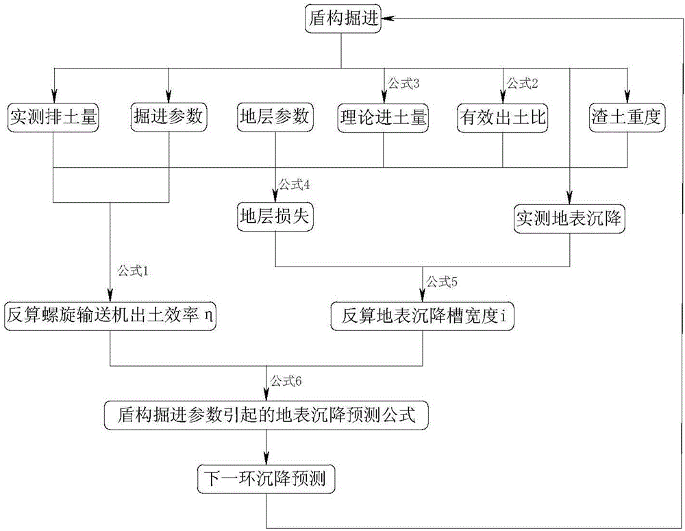
[0037] see figure 1 , the prediction method of land surface subsidence caused by earth pressure balance shield silo entry and discharge, including the following steps:

[0038]Step (1): When the shield tunneling process, when the pressure of the soil bin begins to stabilize, measure the volume V and weight G of the muck discharged by the shield within the time T of one ring segment, and divide the weight G of the muck by the weight of the dregs Soil volume V, get the weight of muck γ 1 ;Record the excavation speed v, the screw conveyor speed N, and the added weight of the slag improvement material G 1 ;

[0039] Step (2): Combining the gravity G of the muck discharged by the screw conveyor during shield tunneling and the parameters of the shield itself, namely the thread pitch P and the diameter of the screw mandrel D 1 and the inner diameter of the screw machine D 2 ,...


PUM


Abstract

The invention discloses a method for predicting ground settlement caused by soil bin soil entering and discharge through a soil pressure balance shield. The method comprises the following steps: according to tunneling data and ground settlement data of the shield at the initial tunneling stage, through deducing a relation between a shield tunneling parameter (N/v) and ground loss caused by shield soil discharge, inversely computing screw conveyor soil discharge efficiency eta and ground settlement trough width I; establishing a ground settlement prediction formula during the next tunneling of the shield; selecting a next tunneling parameter and substituting into the formula to compute, so that the prediction of a ground settlement value is realized. The method disclosed by the invention is simple and practical and good in adaptability; the relation between the soil bin soil entering and discharge and the ground settlement is established from a shield tunneling mechanism, so that ground settlement caused by the tunneling parameter can be accurately predicted, and excessive upheavals and settlement values are prevented from being generated on the ground.

Description

technical field [0001] The invention relates to a method for predicting land surface subsidence, in particular, the invention relates to a method for predicting land surface subsidence caused by earth pressure balance shield tunnel entry and discharge. Background technique [0002] As one of the important construction methods for tunnel excavation in soft ground, the earth pressure balance shield method is widely used in the construction of subways in major cities at home and abroad. However, excessive surface uplift and subsidence caused by earth pressure balance shield excavation occur from time to time, and there is still a lack of practical and accurate prediction methods for surface subsidence caused by shield excavation. [0003] Surface subsidence results from formation loss. The ground surface loss caused by shield excavation is mainly composed of three parts, including: 1) stratum loss caused by soil bin entering and discharging soil when the shield cutter head rea...

Claims


Application Information

Patent Timeline
IPC IPC(8): G06F17/50
CPCG06F30/13
Inventor 王树英瞿同明阳军生何卫胡钦鑫傅金阳
Owner CENT SOUTH UNIV
Why Eureka
Try Eureka