Rotary electric machine

A subgroup, laminate technology, applied in electrical components, electromechanical devices, electric components, etc., can solve problems such as high cost, and achieve the effect of improving cooling and good cooling possibility

Inactive Publication Date: 2017-01-04
MOTEURS LEROY SOMER
View PDF16 Cites 2 Cited by
  • Summary
  • Abstract
  • Description
  • Claims
  • Application Information

AI Technical Summary

Problems solved by technology

[0010] The frame implies a relatively high cost and forms an additional thermal barrier to the outside

Method used


Image

  • Rotary electric machine
  • Rotary electric machine
  • Rotary electric machine

Examples


Embodiment Construction

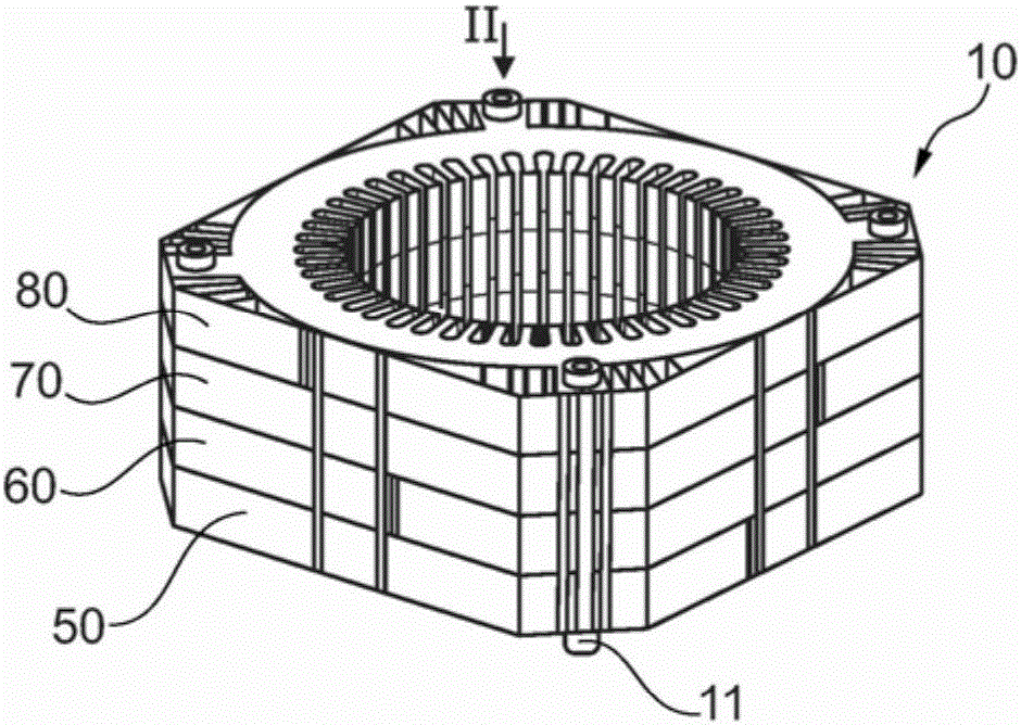
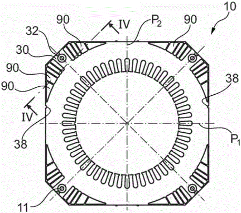
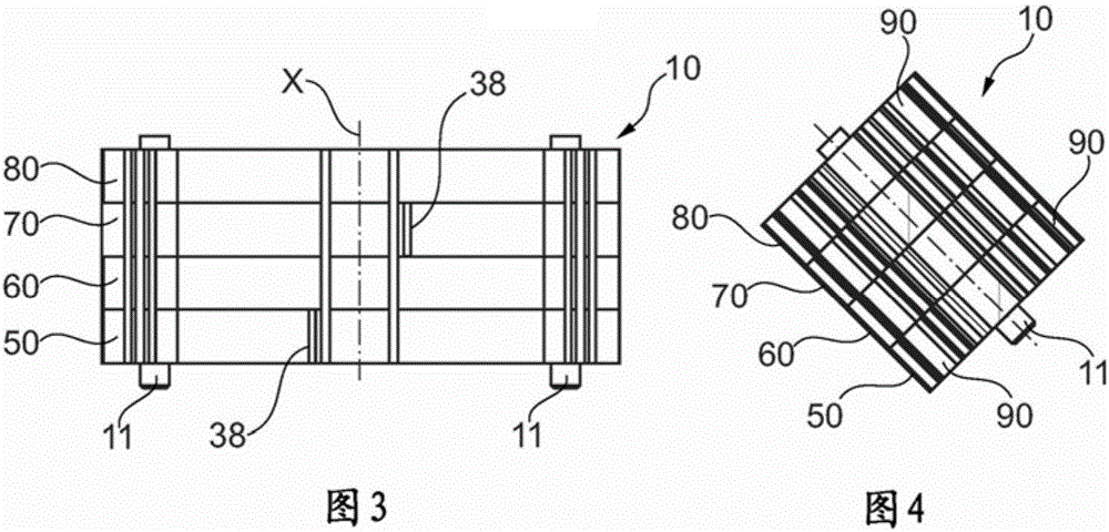
[0053] figure 1 One example of a stator lamination pack 10 of a rotating electric machine according to the invention is depicted to FIG. 4 . The rotating electric machine may be a synchronous or asynchronous permanent magnet or an alternator or electric motor. Figure 10 to Figure 12 An example of a complete motor 1 is depicted in .

[0054] The set 10 includes a plurality of superimposed magnetic laminations 20, one magnetic lamination in the plurality of superimposed magnetic laminations 20 Figure 5 are depicted separately in front view.

[0055] Each laminate 20 is made, for example, of magnetic steel covered on its opposite face by an electrically insulating varnish in a manner known per se.

[0056] In the example considered, the electric machine has an internal rotor, and each laminate 20 comprises a central opening 21 for passage of the rotor, into which an open slot 22 is cut into the laminate. and is intended to receive the electrical conductors of the stator win...


PUM


Abstract

The invention relates to an electric machine comprising a stator, this stator comprising a set (10) of magnetic laminations which is made up of at least one first subset (50) and of at least one second subset (60) adjacent to the first the laminations of the first and second subsets having parts which become superposed, each comprising at least one closed channel formed within the laminations, the laminations being identical but angularly offset from one another by an angle 360 degrees / n about the axis of the machine, where n is a non-zero integer, the laminations being without symmetry in a rotation by 360 degrees / n so that the parts of the laminations thus offset which become superposed are nonidentical and create the said perturbation in the flow at the transition between the channels of the first and second subsets.

Description

technical field [0001] The invention relates to a rotating electrical machine comprising a magnetic laminate stack at a stator. Background technique [0002] Conventionally, the laminate forms slots that receive the windings of the stator windings of the electrical machine. [0003] In order to make it easier to cool the electric machine, it is known practice to form the laminate with cooling channels or cooling fins. [0004] Furthermore, motors can be classified into two categories: namely, framed motors and frameless motors. [0005] In the first category, the stator lamination pack is housed in a frame. In the second category, the outer surface of the electrical machine is directly defined by the stack of laminates. [0006] Application FR 2 927 736, patents US 5 331 238 and US 7 633 194 disclose motors with frames. The set of stator laminations may include sub-sets provided with cooling fins arranged in a staggered configuration along the electric machine to create ...

Claims


Application Information

Patent Timeline
Patent Type & Authority Applications(China)
IPC IPC(8): H02K1/20
CPCH02K1/20H02K2213/03H02K1/185H02K5/00H02K5/04H02K5/225H02K7/14H02K9/06H02K2201/06H02K1/16
Inventor 迈克尔·麦克莱兰伊万·德亚克奥雷利安·卡里奇亚历克西斯·迪托
Owner MOTEURS LEROY SOMER
Why Eureka
Try Eureka