Tooling structure for mounting rotor magnetic pole component of permanent magnet generator

A technology for permanent magnet generators and rotor poles, which is applied to electric components, manufacturing motor generators, electromechanical devices, etc., can solve the problems of large repulsion force of a single magnetic pole and slow assembly efficiency, so as to improve assembly efficiency, shorten assembly time, The effect of ensuring installation accuracy

Active Publication Date: 2017-01-04
GUANGDONG MINGYANG WIND POWER IND GRP CO LTD
View PDF6 Cites 8 Cited by
  • Summary
  • Abstract
  • Description
  • Claims
  • Application Information

AI Technical Summary

Problems solved by technology

[0002] At present, the rotor pole assembly of the wind permanent magnet synchronous generator is composed of a plurality of pole boxes embedded with permanent magnets, a square screw, and a pole pressure

Method used


Image

  • Tooling structure for mounting rotor magnetic pole component of permanent magnet generator
  • Tooling structure for mounting rotor magnetic pole component of permanent magnet generator

Examples


Example Embodiment

[0014] The present invention will be further described below in conjunction with specific examples.

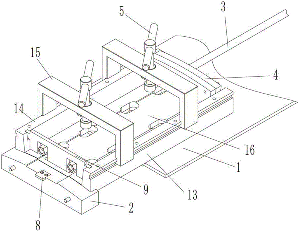
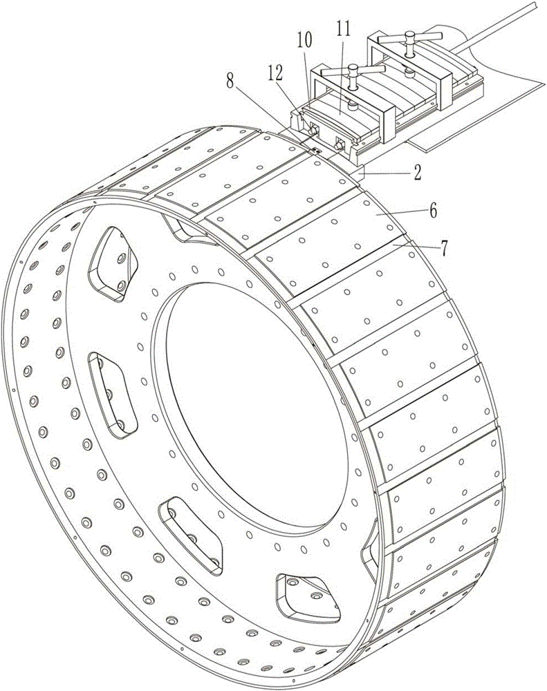
[0015] like figure 1 and figure 2 As shown, the tooling structure for installing the permanent magnet generator rotor pole assembly described in this embodiment includes a magnetic steel base 1, an alignment plate 2, a hydraulic rod 3, a thrust plate 4, and a compression screw 5; The steel base 1 is installed on the rotor support 6 of the permanent magnet generator through the alignment plate 2, wherein the magnetic steel base 1 and the alignment plate 2 are connected by bolts, and the rotor support 6 and the alignment plate 2 are connected by bolts , the outer peripheral surface of the rotor bracket 6 is evenly provided with a plurality of guide grooves 7 along its circumference, and an alignment block matching the guide grooves 7 is installed on the end of the alignment plate 2 connected with the rotor bracket 6 8. The alignment block 8 protrudes from the alignment plate ...


PUM


Abstract

The invention discloses a tooling structure for mounting a rotor magnetic pole component of a permanent magnet generator. The tooling structure for mounting the rotor magnetic pole component of the permanent magnet generator comprises a magnetic steel base, an alignment plate, a hydraulic rod, a thrust plate and pressing screw rods; the magnetic steel base is mounted on a rotor bracket of the permanent magnet generator through the alignment plate, a plurality of guide grooves are formed in the peripheral surface of the rotor bracket, an alignment block is arranged on the alignment plate, and the magnetic steel base is inserted into the guide grooves through the alignment block to be positioned and mounted automatically; the hydraulic rod is connected with the thrust plate through threads, and an external driving device provides power to the hydraulic rod; an installation position for accommodating the rotor magnetic pole component is reserved on the magnetic steel base, and configured with a detachable baffle plate for blocking a magnetic pole pressing plate and a magnetic pole firstly placed at the installation position by the rotor magnetic pole component, the other magnetic poles are pushed to the installation position by the thrust plate, in the assembling process of the rotor magnetic pole component, the magnetic pole is pressed closely by the pressing screw rods mounted on the magnetic steel base. By adopting the tooling structure disclosed by the invention, the assembling efficiency and the assembling reliability can be improved.

Description

technical field [0001] The invention relates to the technical field of equipment for installing permanent magnet generator rotor magnetic poles, in particular to a tooling structure for permanent magnet generator rotor magnetic pole assembly installation. Background technique [0002] At present, the rotor pole assembly of the wind permanent magnet synchronous generator is composed of a plurality of pole boxes embedded with permanent magnets, a square screw, and a pole pressure plate, etc., and then the pole assembly is installed on the rotor bracket. The repulsive force between them is very large, which leads to certain risks in the assembly process and slow assembly efficiency. Contents of the invention [0003] The purpose of the present invention is to overcome the shortcomings and deficiencies of the prior art, and provide a tooling structure for installing permanent magnet generator rotor pole assemblies that can improve assembly efficiency and assembly reliability. ...

Claims


Application Information

Patent Timeline
IPC IPC(8): H02K15/03
CPCH02K15/03
Inventor 刘冰鑫龚磊罗荣锋杨云章政华陈海游
Owner GUANGDONG MINGYANG WIND POWER IND GRP CO LTD
Why Eureka
Try Eureka