Video data distribution unit, device and system

A technology of video data and distribution unit, applied in the field of communication, can solve the problem of quantization distortion processing delay and so on

Active Publication Date: 2017-01-04
ZHEJIANG DAHUA TECH CO LTD
View PDF4 Cites 9 Cited by
  • Summary
  • Abstract
  • Description
  • Claims
  • Application Information

AI Technical Summary

Problems solved by technology

[0006] Embodiments of the present invention provide a video distribution unit, device, and s

Method used


Image

  • Video data distribution unit, device and system
  • Video data distribution unit, device and system
  • Video data distribution unit, device and system

Examples


Embodiment 1

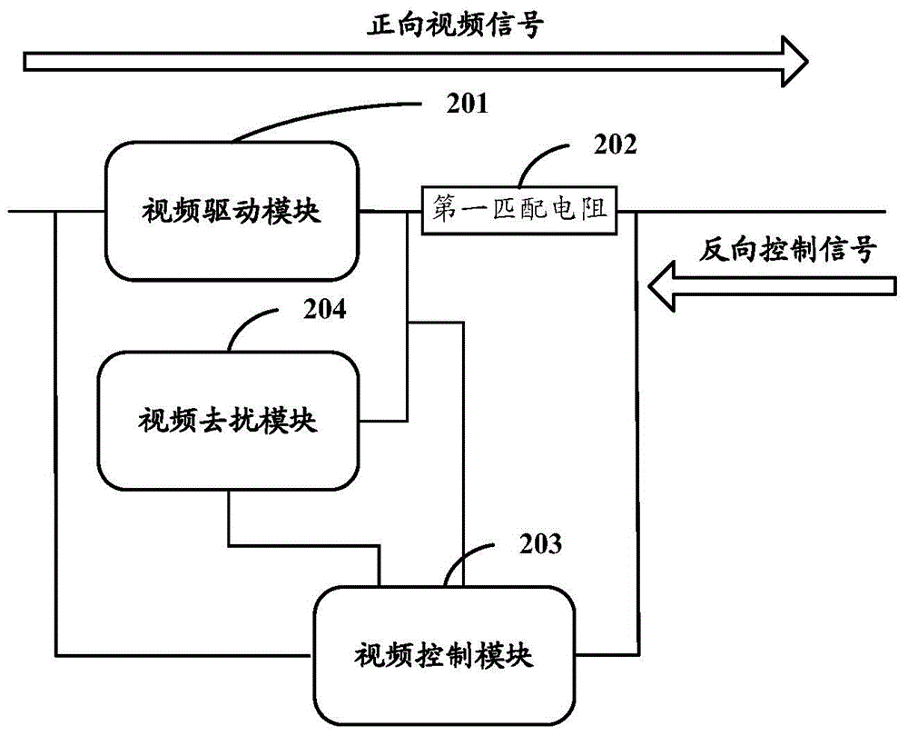
[0042] In the embodiment of the present invention, a video data distribution unit 2 is firstly introduced, such as figure 2 As shown, the video data distribution unit 2 includes a video driver module 201, a first matching resistor 202, a video control module 203, and a video descrambling module 204:

[0043] The video driving module 201 is configured to receive the video data transmitted from the video data acquisition device, and transmit the video data forward to the video data receiving device through the first matching resistor 202 .

[0044] A video control module 203, configured to acquire the voltage of the first node at the video data output end in the first matching resistor 202, and acquire the voltage at the second node at the video data input end of the first matching resistor 202, And when it is determined that the obtained voltage of the first node is higher than the voltage of the second node, extracting the reverse control signal in the blanking area of ​​the v...

Embodiment 2

[0060] Such as image 3 As shown, a video data distribution device 3 provided in Embodiment 2 of the present invention includes at least one video data distribution unit 2. In fact, the connection relationship of the video data distribution device 3 is similar to that of the prior art, except that the video data distribution unit 2 is different from the prior art, and the difference has been introduced above, and will not be repeated here.

Embodiment 3

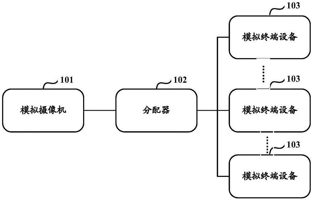
[0062] Such as Figure 4 As shown, a video data distribution system 4 provided by an embodiment of the present invention includes: a video data collection device 401, a video data receiving device 402, a video data distribution device 403 and a third matching resistor R3.

[0063] Wherein, the video data distribution device 403 is used to receive video data, forward transmit the video data to the video data receiving device, and receive the reverse control sent by the video data receiving device 402 in the blanking area of ​​the video data. signal, extracting the reverse control signal, and controlling the voltages of the two nodes of the first matching resistor included in itself, so as to control the extracted reverse control signal not to be transmitted back. Thus, the extracted reverse control signal is transmitted to the video data collection device 401 .

[0064] One node of the third matching resistor R3 is grounded, and the other node is connected to the fourth node o...


PUM


Abstract

The present invention discloses a video data distribution unit, device and system. The main content of the present invention is that: a video driving module receives the video data and forward transmits the video data to a video data receiving device via a first matching resistor, and a video control module obtains the voltage of a first node in the first matching resistor and located at a video data output end and the voltage of a second node located at a video data input end, extracts a reverse control signal in a blanking zone when the voltage of the first node is higher than the voltage of the second node, transmits the extracted reverse control signal to a video data acquisition device and utilizes the reverse control signal to trigger a video interference elimination module to control the voltages of the two nodes of the first matching resistor, so that the extracted reverse control signal is not transmitted back, and the correct and continuous extraction and the forward transmission of the reverse control signal are guaranteed. Moreover, the digital analog conversion is not needed, and the quantization distortion and processing delay problems brought by the digital processing are avoided.

Description

technical field [0001] The present invention relates to the field of communication technology, in particular to a video data distribution unit, equipment and system. Background technique [0002] At present, there are many analog video interfaces with coaxial anti-control function in the industry, such as: HDCVI, HDTVI, AHD, etc., and the principle of this type of analog video interface is to use the blanking area of ​​video data to transmit the reverse control signal, so that Realize the coaxial anti-control function. [0003] It is based on this principle of coaxial anti-control, for this kind of analog video interface distributor (also called distribution equipment), the traditional solution is to use digital processing, because the anti-control signal is in the blanking area, so It is necessary to use a processor to analyze the current video and find the blanking area in order to extract the anti-control signal. [0004] As shown in FIG. 1( a ), it is a schematic struc...

Claims


Application Information

Patent Timeline
IPC IPC(8): H04N5/268H04N5/14
Inventor 洪小其邓志吉张兴明
Owner ZHEJIANG DAHUA TECH CO LTD
Why Eureka
Try Eureka