Integrated camera structure of chip mounting machine

A technology that integrates cameras and placement machines. It is applied in the direction of cameras, optics, instruments, etc. It can solve the problems of not meeting the requirements of the distance between suction nozzles, affecting the speed of image recognition, and time-consuming image processing, so as to avoid unclear images and shorten the time taken for taking pictures. Time, the effect of reducing the number of photos taken

Inactive Publication Date: 2017-01-04
广东木几智能装备有限公司
View PDF10 Cites 3 Cited by
  • Summary
  • Abstract
  • Description
  • Claims
  • Application Information

AI Technical Summary

Problems solved by technology

The existing bottom mirror vision system of placement machines has the following disadvantages: 1. The structure of the bottom mirror vision system is a bottom mirror camera, and the bottom mirror camera takes pictures of multiple placement heads in sequence. The camera will take pictures 4 times, which not only takes a long time to take pictures, but also takes time when processing multiple images
2. The camera control adopts the software control method. When the single axis moves to the position where the patch head to be processed moves directly above the bottom mirror camera, an instruction is given to the software. After receiving this instruction, the software sends a trigger signal to the bottom mirror camera to realize a photoshoot. Image processing is time consuming due to software processing
4. If the camera movement speed is increased to reduce the time for taking pictures, the camera movement speed is faster, which will cause image smearing and affect the image recognition speed
5. If multiple independent cameras are installed together to take pictures at the same time, the size of the camera itself will not meet the distance requirements of the nozzles

Method used


Image

  • Integrated camera structure of chip mounting machine
  • Integrated camera structure of chip mounting machine

Examples


Embodiment Construction

[0020] The specific embodiment of the present invention will be further described below in conjunction with accompanying drawing:

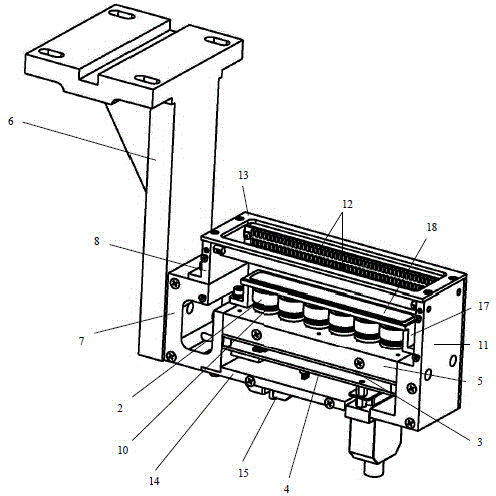
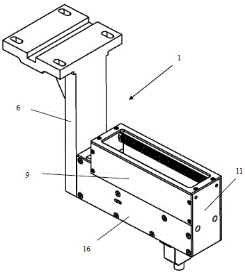
[0021] Such as Figure 1-2 As shown, an integrated camera structure of a mounter includes a camera mount 1 and an integrated camera, the integrated camera is composed of a camera lens 2 connected to an integrated camera control board, and the integrated camera control board is connected to an industrial motherboard , the integrated camera control board is composed of an image sensor induction board 3 and an image data processing board 4 connected, the camera mount 1 is provided with a camera lens holder 5, and a row of six camera lenses 2 is arranged on the camera lens holder 5, The camera lens 2 is connected to the image sensor sensing board 3, the hardware trigger interface is set on the image data processing board 4, and the motion control card on the industrial mainboard gives the trigger signal to the hardware trigger interface to realize the...


PUM


Abstract

The invention provides an integrated camera structure of a chip mounting machine. The integrated camera structure comprises a camera installation seat and an integrated camera, wherein the integrated camera is formed by connecting camera lenses and an integrated camera control board card, the integrated camera control board card is connected with an industrial mainboard and is formed by connecting an image sensor induction board and an image data processing board, a camera lens seat is arranged in the camera installation seat, a plurality of rows of camera lenses are arranged on the camera lens seat, the camera lenses are connected with the image sensor induction board, a hardware trigger interface is arranged on the image data processing board, a moving control card on the industrial mainboard gives a trigger signal to the hardware trigger interface so as to trigger the integrate camera to shoot in a moving way when a chip mounting head moves to a certain position, a kilomega network transmission interface is arranged on the image data processing board, and image data after the integrated camera shoots in the moving way is sent back to the industrial mainboard for image post processing.

Description

technical field [0001] The invention relates to a camera structure, in particular to an integrated camera structure of a placement machine. Background technique [0002] The placement machine is an important equipment in the field of SMT (Surface Mount Technology). With the development of science and technology, the types of electronic components are increasing, the volume is getting smaller and other factors, and the requirements for the placement machine are getting higher and higher. , mainly focusing on speed, accuracy, stability and other aspects. The speed factor is an important performance indicator that determines the placement machine, and is also an important indicator for the placement machine user to choose equipment. The main factors affecting the placement speed of the placement machine can be summed up in two aspects: first, the movement speed of the placement machine in each axis direction; second, factors such as image recognition of the bottom mirror camer...

Claims


Application Information

Patent Timeline
Patent Type & Authority Applications(China)
IPC IPC(8): H05K13/08H05K3/30G03B29/00
Inventor 吴志达程治国吴凡
Owner 广东木几智能装备有限公司
Why Eureka
Try Eureka