Self-propelled canal irrigation device and irrigation method for same
An irrigation device and self-propelled technology, applied in watering devices, botany equipment and methods, horticulture, etc., can solve the problems of low degree of automation and high labor intensity, and achieve convenient and efficient construction, reduce the amount of openings, and reduce occupation ground effect
- Summary
- Abstract
- Description
- Claims
- Application Information
AI Technical Summary
Problems solved by technology
Method used
Image
Examples
Embodiment 1
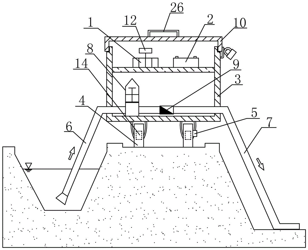
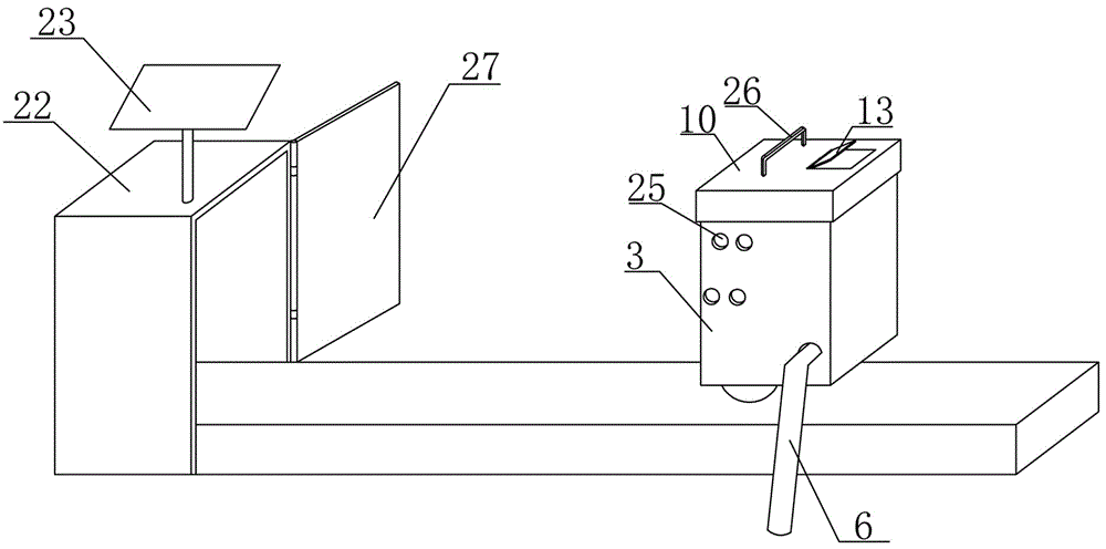
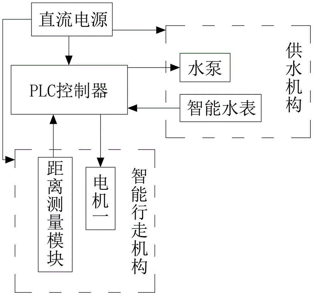
[0040] Such as Figure 1-Figure 3 As shown, a self-propelled canal irrigation device includes an intelligent walking mechanism, a water supply mechanism, a PLC controller 1 and a DC power supply 2, the DC power supply 2 provides power for the intelligent walking mechanism, the water supply mechanism and the PLC controller, and the DC power supply 2 is The rechargeable power supply and the PLC controller are connected to the touch screen 12 through a serial port communication line to facilitate automatic control of the irrigation device.
[0041] Intelligent walking mechanism comprises vehicle frame 3, the moving wheel 4 that is arranged on vehicle frame 3 bottoms, the distance measuring module 5 that is arranged on moving wheel 4 and the motor-14 that drives moving wheel 4 to run, the distance measuring module 5 in the present embodiment Be odometer sensor; Wherein vehicle frame 3 is provided with waterproof cover 10, and waterproof cover 10 is directly covered on vehicle fram...
Embodiment 2
[0050] The structure of this embodiment is basically the same as that of Embodiment 1, the difference is: as Figure 4-Figure 6 As shown, the pumping device 8 includes a motor two 15, an L-shaped support 24 fixedly connected to the output end of the two motors 15, the L-shaped support 24 is connected to the rotating rod 16 by rotating the rotating shaft, and the rotating rod 16 bottom is connected to the connecting rod 17 top by rotating the rotating shaft. The piston 18 is fixed at the bottom of the rod 17, and the piston 18 is arranged in the cylinder body 19. One side of the cylinder body 19 is connected to the water inlet pipe 6, and the other side is connected to the water outlet pipe 7. The check valve 2 21 is electrically connected to the PLC controller 1 and the motor 2 15 .
[0051] An irrigation method for a self-propelled canal irrigation device, comprising the following steps:
[0052] (1) Set the water supply and walking distance in PLC controller 1 according to ...
Embodiment 3
[0056] The self-propelled canal irrigation device of the present embodiment has basically the same structure as that of Embodiment 2, the difference is: as Figure 7 As shown, a filter screen 11 is provided at the bottom of the water inlet pipe 6 to filter the water in the channel to prevent the water inlet pipe 6 from being blocked, and protective plates 28 are arranged on both sides of the bottom of the vehicle frame 3 to protect the water inlet pipe 6 and the water outlet pipe 7 , to avoid the phenomenon of dragging the water inlet pipe 6 and the water outlet pipe 7 on the ground, so as to increase the service life of the water inlet pipe and the water outlet pipe.
PUM
 Abstract
Description
Claims
Application Information
 - R&D
- Intellectual Property
- Life Sciences
- Materials
- Tech Scout
- Unparalleled Data Quality
- Higher Quality Content
- 60% Fewer Hallucinations
Browse by: Latest US Patents, China's latest patents, Technical Efficacy Thesaurus, Application Domain, Technology Topic, Popular Technical Reports.
© 2025 PatSnap. All rights reserved.Legal|Privacy policy|Modern Slavery Act Transparency Statement|Sitemap|About US| Contact US: help@patsnap.com


