Supercharge Your Innovation With Domain-Expert AI Agents!

Air dust separation device and dust collector

A technology for separating devices and air and dust, which is applied in the direction of vacuum cleaners, suction filters, cleaning equipment, etc. It can solve the problems of damaging the motor, reducing the service life of the motor, reducing the air environment, etc., and achieves the effect of increasing speed, simple cleaning, and reducing cleaning frequency

Active Publication Date: 2017-01-11
SUZHOU HAIGE ELECTRICAL TECH CO LTD
View PDF6 Cites 6 Cited by
  • Summary
  • Abstract
  • Description
  • Claims
  • Application Information

AI Technical Summary

Problems solved by technology

[0003] Therefore, the filter structure in the dust box determines the dust collection effect and air permeability of the vacuum cleaner. If the filter structure in the dust box is too simple, the air sucked into the dust box will return to the room with a large amount of dust, mixed with When the dusty air passes through the motor, it not only has a limited cooling effect on the motor, but also easily blocks the motor and damages the motor. What is more serious is that the dust near the surface is discharged into the room through the vacuum cleaner, which greatly reduces the The indoor air environment affects people's respiratory health, which seriously violates the original intention of the vacuum cleaner to clean the air; if a filter is added to affect the air circulation just to enhance the effect of filtering dust, then as a large amount of dust accumulates on the filter, the dust will Blocking the filter will greatly affect the air permeability of the vacuum cleaner, making it difficult for the airflow to flow through the motor to the outside of the vacuum cleaner. Service life
[0004] In the prior art, the dust box is equipped with a cyclone filter structure and a filter grid structure. The air entering the dust box first passes through the cyclone filter structure, and the airflow rotates at a high speed, and the larger particles of impurity dust are preferentially thrown out, which will not affect the secondary filter. The filter parts and filter holes are blocked, but the inner cup is a structure with the opening facing upwards. Under the disturbance of the air flow, some separated ash will be sucked into the next filter link with the air again, which affects the separation efficiency; and, the dust Falling into the bottom of the cup, there is still a dead zone of dust at the bottom of the cup, and the inner cup must be removed to clean it thoroughly, which is inconvenient to clean; it enters multiple cyclone pipes through filter holes, diversion holes and cyclone inlets, and the airflow flows along the collection in the cyclone pipes. The outer wall of the air duct rotates downward at high speed to complete the secondary cyclone filtration; the multi-stage cyclone filtration method can efficiently filter and separate the fine dust entrained in the airflow; In the middle, the airflow with fine dust enters the cavity between the outer wall of the inner air collecting tube and the inner side of the outer cup and rotates, which is easy to pollute the inner side of the outer cup and the outer side of the inner cup. It can be cleaned after being disassembled, which is inconvenient to clean

Method used


Image

  • Air dust separation device and dust collector
  • Air dust separation device and dust collector
  • Air dust separation device and dust collector

Examples


Embodiment 1

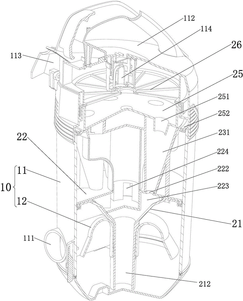
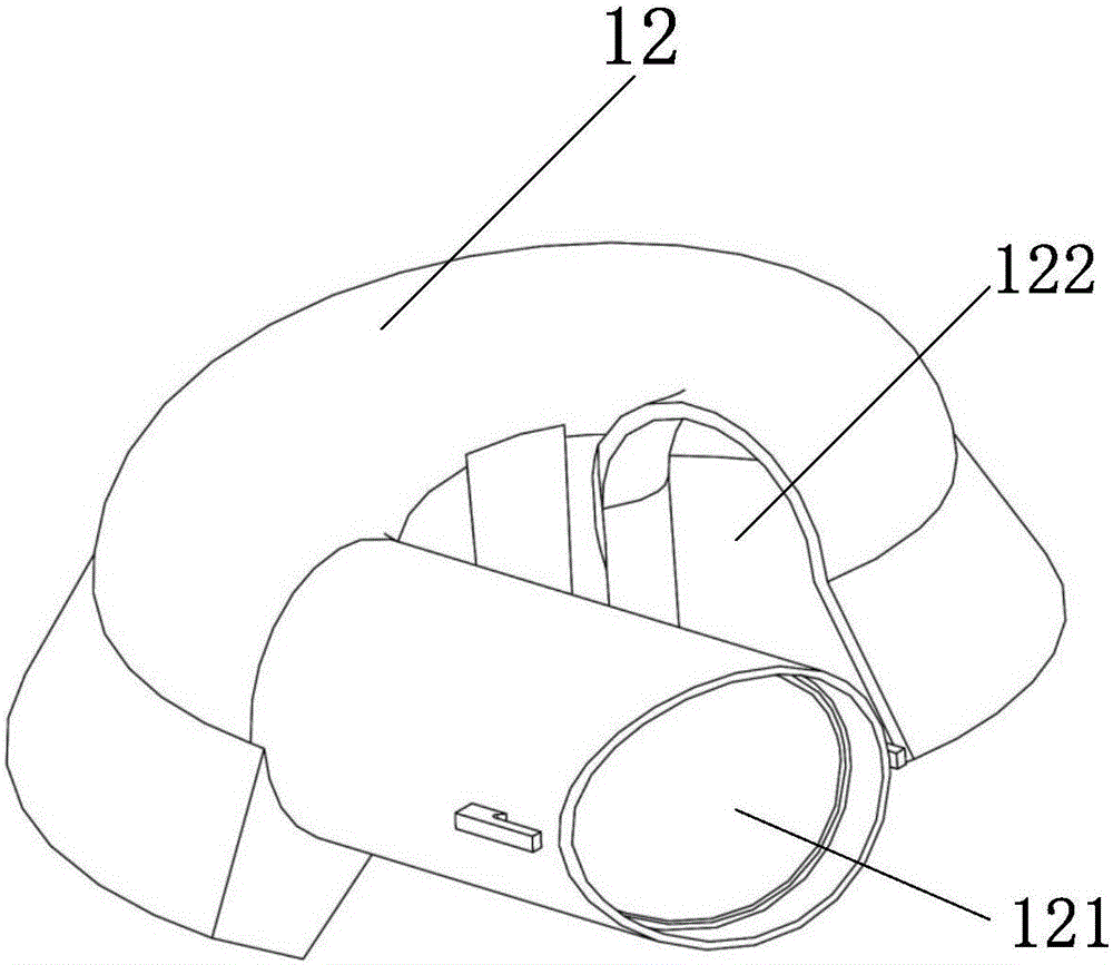
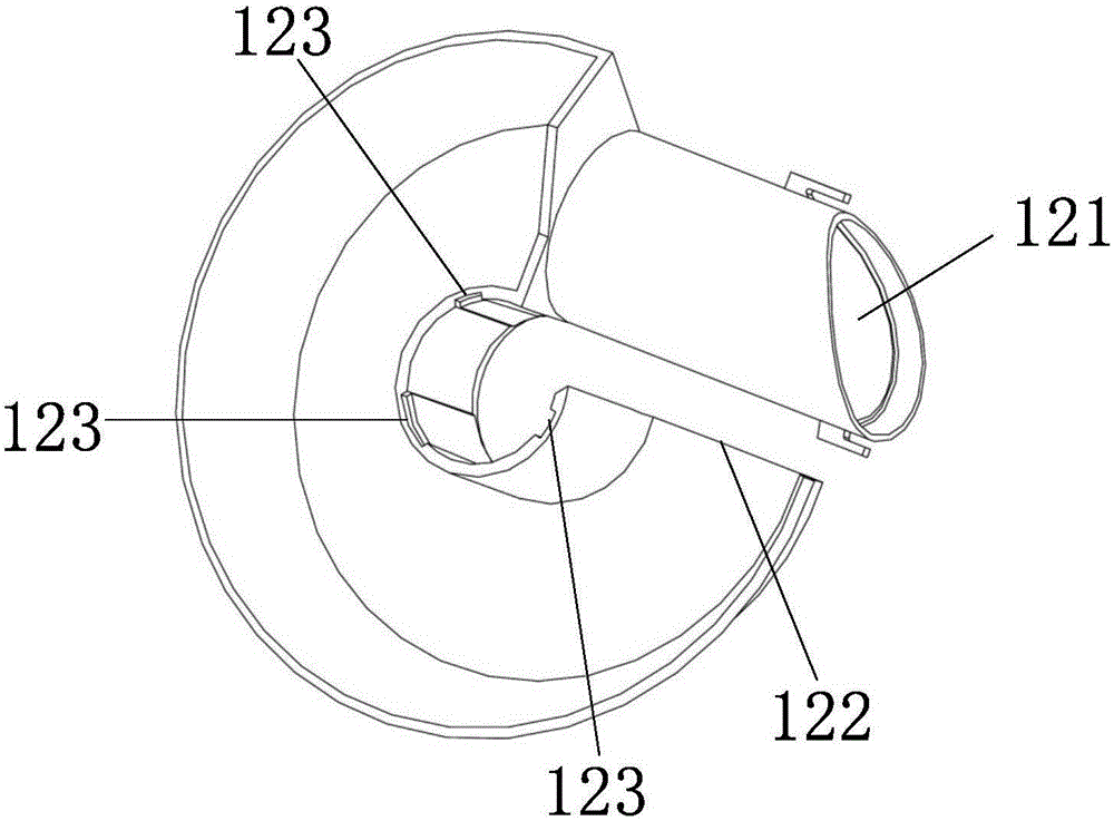
[0056] like figure 1 , Fig. 2(a), Fig. 2(b), Fig. 3(a) and Fig. 3(b), as shown, the embodiment of the present invention provides a kind of gas-dust separation device, comprising: dust cup 10 and gas-dust separation device 20. The dust cup 10 includes an outer cup 11 and an inner cup 12 having a cavity. The inner cup 12 is set in the outer cup 11 with the opening facing down; the outer cup 11 and the inner cup 12 are respectively provided with a connected first air inlet 111 and a second air inlet 121; the inner cup 12 is provided with a first outlet near the top. The tuyere 122; the gas-dust separator 20 includes a dust collection funnel 21, the dust collection funnel 21 is located inside the outer cup 11 and sealed and inserted above the inner cup 12; the dust collection funnel 21 is provided with a filter grid hole 211; wherein, the first air inlet 111. The second air inlet 121, the first air outlet 122, and the filter grid hole 211 form an airflow path; the inner cup 12 i...

Embodiment 2

[0071] On the basis of Embodiment 1, this embodiment provides a vacuum cleaner including the gas-dust separation device described in Embodiment 1. The vacuum cleaner is provided with a motor and its casing, an air-dust separation device and a floor mop. Among them, the motor housing is provided with an air extraction power device, and the motor housing is provided with a gas inlet and a gas outlet; the outer cup 11 is provided with an upper cover 112 with a sealing cover arranged above the air collecting plate 25 and the filter cotton 26. The cover 112 is provided with a second air outlet 113 . Then, the second air outlet 113 of the upper cover 112 is communicated with the air inlet of the motor housing; the floor brush is communicated with the first air inlet 111 of the outer cup 11 of the air-dust separation device through the connecting piece.

[0072] The process of using the vacuum cleaner is: connect the suction power device to the power supply, hold the floor brush, an...


PUM


Abstract

The invention discloses an air dust separation device and a dust collector. The air dust separation device comprises a dust cup and an air dust separator, the dust cup comprises an outer cup and an inner cup with a downward opening, the inner cup is arranged in the outer cup, a first air inlet and a second air inlet are communicated and correspondingly formed in the outer cup and the inner cup respectively, a first air outlet is formed in the top of the inner cup, the air dust separator comprises a dust-collecting hopper which is positioned on the inner side of the outer cup and connected to the upper portion of the inner cup in an inserted manner, the dust-collecting hopper is provided with a filtering gate hole, the first air inlet, the second air inlet, the first air outlet and the filtering gate hole form an airflow passage, the inner cup is used for primarily separating and collecting airflow rotationally entering the second air inlet, and the filtering gate hole is used for secondarily separating the airflow which is primarily separated. The inner cup with the downward opening is used for collecting dust, collecting and cleaning of a dust-collecting tube and the inner cup are uncrossed, the air dust separation device is convenient to clean, three-stage separated fine dust is delivered to the dust-collecting tube, the space between the outer side of a cyclone tube and the inner side of the outer cup cannot be polluted, and the air dust separation device has good air dust separation effects by the aid of multi-stage cyclone separation.

Description

technical field [0001] The present invention relates to the technical field of home appliances, and more particularly, to a gas-dust separation device and a vacuum cleaner. Background technique [0002] The vacuum cleaner is a small household appliance that uses the motor to drive the blades to rotate at a high speed, generates negative air pressure in the sealed casing, and absorbs dust. The floor brush, connecting pipe, handle, hose, and main suction pipe enter the dust filter bag in the dust box, the dust is left in the dust filter bag, and the filtered air enters the motor through a layer of filter, which is to prevent the dust bag from breaking. The dust is sucked into a protective barrier of the motor, and the filtered air enters the motor and is discharged into the room again. [0003] Therefore, the filter structure in the dust box determines the cleaning effect and air permeability of the vacuum cleaner. If the filter structure in the dust box is too simple, the ai...

Claims


Application Information

Patent Timeline
IPC IPC(8): A47L9/10A47L9/16A47L9/12A47L9/00
CPCA47L9/00A47L9/102A47L9/12A47L9/1683A47L9/1691
Inventor 陆苏忠杨曾峥周旭潘加文
Owner SUZHOU HAIGE ELECTRICAL TECH CO LTD
Features
  • R&D
  • Intellectual Property
  • Life Sciences
  • Materials
  • Tech Scout
  • Unparalleled Data Quality
  • Higher Quality Content
  • 60% Fewer Hallucinations
Learn More