Eye fundus photography control circuit applying triangular wave illumination capable of raising preset level
A technology of preset level and control circuit, applied in applications, ophthalmoscopes, equipment for testing eyes, etc., can solve the problems of low signal-to-noise ratio of digital signals and affect the signal-to-noise ratio of images, and achieves low device and process requirements, The effect of improving the signal-to-noise ratio and improving the quality
- Summary
- Abstract
- Description
- Claims
- Application Information
AI Technical Summary
Problems solved by technology
Method used
Image

Examples
Embodiment 1
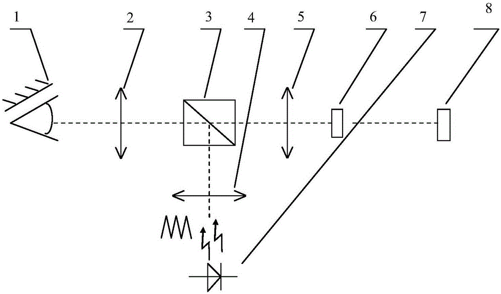
[0034] see figure 1 , the fundus photography control circuit using triangular wave illumination with raised preset level, comprising: connecting eyepiece and objective lens 2, semi-transparent and semi-reflective prism 3, illuminating lens group 4, imaging objective lens 5, image sensor 6, LED lighting lamp 7 and Computer 8, wherein, the eyepiece and objective lens 2, half-reflective prism 3, imaging objective lens 5 and image sensor 6 are arranged in sequence, and an illuminating lens group 4 is arranged between the half-reflective prism 3 and the LED lighting lamp 7;
[0035] Among them, the LED lighting lamp 7 is driven by a triangular wave or sawtooth wave electrical signal with a preset level to generate a beam of triangular wave or sawtooth waveform lighting light, and the triangular wave or sawtooth waveform lighting light passes through the lighting lens group 4, transflective and transflective in turn. The prism 3, the eyepiece and the objective lens 2 irradiate the f...
Embodiment 2
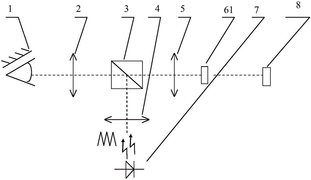
[0056] see figure 2 , the fundus photography control circuit that uses the triangular wave illumination that raises the preset level, the difference between the illumination light control circuit and embodiment 1 is that the image sensor 6 is specifically a CCD image sensor 61, and the illumination light control circuit includes: an eyepiece and an objective lens 2, semi-transparent and semi-reflective prism 3, illumination lens group 4, imaging objective lens 5, CCD image sensor 61, LED lighting lamp 7 and computer 8, wherein, connect eyepiece and objective lens 2, semi-transparent and semi-reflective prism 3, imaging objective lens 5 and CCD image sensors 61 are arranged in sequence, and an illuminating lens group 4 is arranged between the half-transparent prism 3 and the LED illuminating lamp 7;
[0057] Among them, the LED lighting lamp 7 is driven by a triangular wave or sawtooth wave electrical signal with a preset level to generate a beam of triangular wave or sawtooth...
Embodiment 3
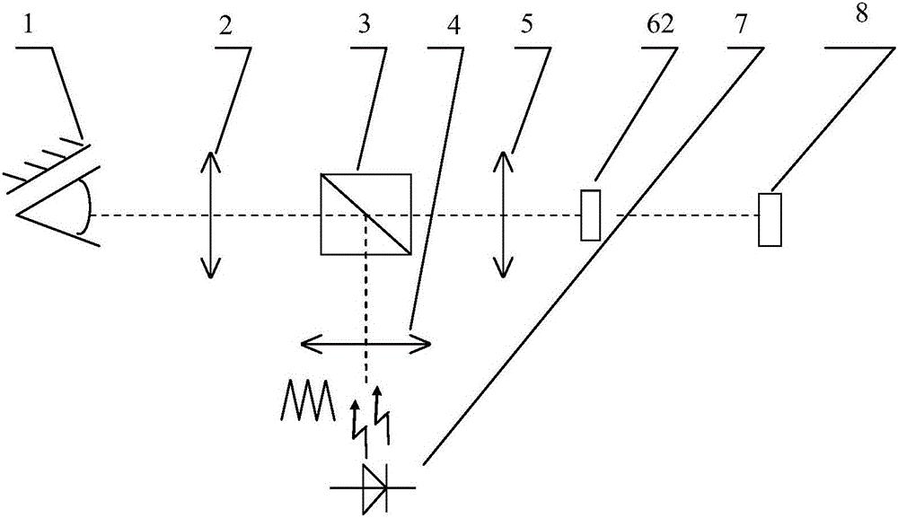
[0062] see image 3 , the fundus photography control circuit that uses the triangular wave illumination that raises the preset level, the difference between the illumination light control circuit and embodiment 1 is that the image sensor 6 is specifically a CMOS image sensor 62, and the illumination light control circuit includes: an eyepiece and an objective lens 2, semi-transparent and semi-reflective prism 3, illumination lens group 4, imaging objective lens 5, CMOS image sensor 62, LED lighting lamp 7 and computer 8, wherein, connect eyepiece and objective lens 2, semi-transparent and semi-reflective prism 3, imaging objective lens 5 and The CMOS image sensors 62 are arranged in sequence, and an illuminating lens group 4 is arranged between the half-transparent mirror 3 and the LED illuminating lamp 7;
[0063] Among them, the LED lighting lamp 7 is driven by a triangular wave or sawtooth wave electrical signal with a preset level to generate a beam of triangular wave or s...
PUM
 Abstract
Description
Claims
Application Information
 - R&D
- Intellectual Property
- Life Sciences
- Materials
- Tech Scout
- Unparalleled Data Quality
- Higher Quality Content
- 60% Fewer Hallucinations
Browse by: Latest US Patents, China's latest patents, Technical Efficacy Thesaurus, Application Domain, Technology Topic, Popular Technical Reports.
© 2025 PatSnap. All rights reserved.Legal|Privacy policy|Modern Slavery Act Transparency Statement|Sitemap|About US| Contact US: help@patsnap.com