Welding clamp of water pump impeller

A technology for welding fixtures and water pump impellers, applied in welding equipment, welding equipment, laser welding equipment, etc., can solve the problems of increasing production costs, reducing production efficiency, and low welding efficiency, achieving zero scrap rate, high production efficiency, and welding Quality and reliable results

Active Publication Date: 2017-01-11
WUHAN CHUTIAN IND LASER EQUIP
View PDF6 Cites 9 Cited by
  • Summary
  • Abstract
  • Description
  • Claims
  • Application Information

AI Technical Summary

Problems solved by technology

[0002] In the prior art, there are manual welding, laser welding, etc. for the welding of the water pump impeller, but the welding efficiency is low, labor intensity, welding quality is low, and the scrap rate is high, which increases the production cost and reduces the production efficiency.

Method used


Image

  • Welding clamp of water pump impeller
  • Welding clamp of water pump impeller
  • Welding clamp of water pump impeller

Examples


Embodiment Construction

[0020] The following examples are used to illustrate the present invention, but are not intended to limit the scope of the present invention.

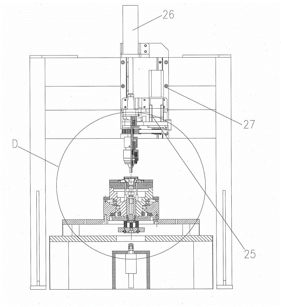
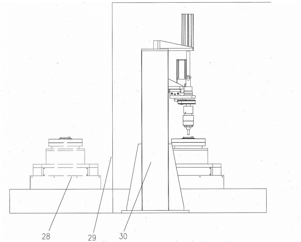
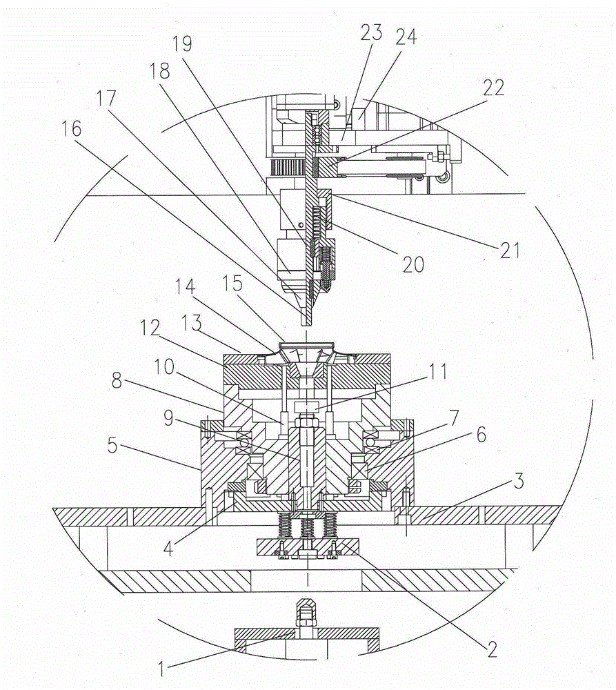
[0021] see Figure 1-Figure 6 , a water pump impeller welding jig related to the present invention is composed of a rotating base, a mold base, a compression rotating device, a friction transmission pair, a gantry frame, a discharge device, and a one-dimensional numerical control workbench group, wherein the mold base is installed on the rotating On the base, the mold base is coaxial with the rotating base, and the rotating base is installed on the one-dimensional numerical control workbench; the pressing and rotating device is installed on the gantry frame, and one end of the friction transmission pair is installed on the rotating and pressing device, and the other end Installed on the mold base, the unloading device is installed under the rotating base, and the gantry is installed across the rotating base. Adjusting the gantry and pr...


PUM


Abstract

The invention relates to a welding clamp of a water pump impeller. The welding clamp comprises a rotating base, a mold seat, a pressing and rotating device, a friction transmission pair, a portal frame, a discharging device and a one-dimensional numerical control workbench. The mold seat is mounted on the rotating base and is coaxial with the rotating base, and the rotating base is mounted on the one-dimensional numerical control workbench. The pressing and rotating device is mounted on the portal frame. One end of the friction transmission pair is mounted on the pressing and rotating device, and the other end of the friction transmission pair is mounted on the mold seat. The discharging device is mounted on the lower portion of the rotating base. The portal frame is mounted above the rotating base in a stretching-over manner. It can be guaranteed that a rotating shaft of the pressing and rotating device and the rotating base are coaxial by adjusting the portal frame and the pressing and rotating device. Compared with a traditional welding device, the welding clamp is simple and fast in clamping and accurate in locating; through combination with the modern laser welding process, fast welding can be achieved; the welding quality is reliable; the zero rejection rate is achieved; the production efficiency is high; and the labor intensity is low.

Description

technical field [0001] The invention relates to a welding device. Specifically relates to a water pump impeller welding fixture. Background technique [0002] In the prior art, there are manual welding, laser welding, etc. for the welding of the water pump impeller, but the welding efficiency is low, the labor intensity, the welding quality are low, and the scrap rate is high, which increases the production cost and reduces the production efficiency. Contents of the invention [0003] The object of the present invention is to provide a welding jig for water pump impeller with accurate positioning, reliable welding and high efficiency. [0004] In order to achieve the above object, the present invention has the following technical solutions: [0005] The invention relates to a water pump impeller welding fixture, which includes a rotating base, a mold base, a pressing and rotating device, a friction transmission pair, a gantry frame, an unloading device, and a one-dimensi...

Claims


Application Information

Patent Timeline
Patent Type & Authority Applications(China)
IPC IPC(8): B23K26/70B23K37/04B23K37/047
CPCB23K37/0435B23K37/047
Inventor 周刚彭琦明
Owner WUHAN CHUTIAN IND LASER EQUIP
Why Eureka
Try Eureka