Numerical control lathe

A technology for CNC lathes and machine tool spindles, which is applied in the field of CNC lathes, can solve problems such as bearing life that affects the machining quality of workpieces, inaccurate installation positions, poor accuracy and stability, and achieves the effect of eliminating potential safety hazards, easy processing, and ensuring normal work.

Inactive Publication Date: 2017-01-11
颜声林
View PDF6 Cites 0 Cited by
  • Summary
  • Abstract
  • Description
  • Claims
  • Application Information

AI Technical Summary

Problems solved by technology

It is difficult to guarantee such a high precision in the processing of general briquetting nuts, so the precision of the main shaft is often out of tolerance during assembly, and finally the tightness of the round nut has to be adjusted repeatedly to barely meet the requirements, but the result is often that the bearing Too tight, poor precision stability, inaccurate installation position, uneven clearance, resulting in high temperature rise during operation, high noise, severe vibration, affecting the processing quality of the workpiece and the life of the bearing
However, for tapered roller bearings used in heavy-duty CNC machine tools, the bearing load is large, the operation is stable, and when the precision is adjusted well, the accuracy of the machine tool is maintained better, but it is not very beneficial for light and high-speed machine tools.

Method used


Image

  • Numerical control lathe
  • Numerical control lathe

Examples


Embodiment Construction

[0015] The technical solution of this patent will be further described in detail below in conjunction with specific embodiments.

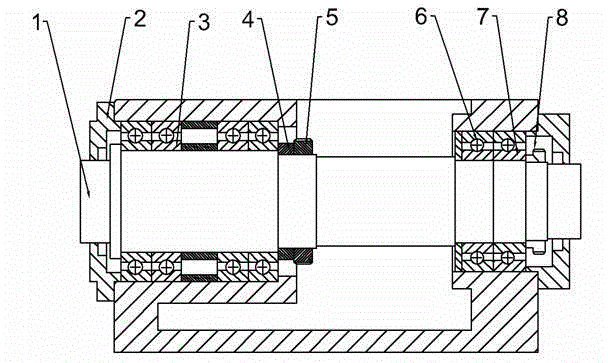
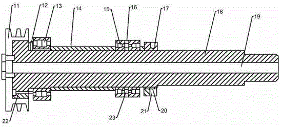
[0016] see Figure 1-2 , a numerically controlled lathe, comprising a workbench, on which a main shaft structure and a processing structure are arranged, and the main shaft structure comprises a machine tool main shaft 1, on which a first angular contact ball bearing 3 and a second angular contact ball bearing 3 are mounted. Ball bearing 6, the outer side of the first angular contact ball bearing 3 is provided with a flange 2, the inner side of the first angular contact ball bearing 3 is provided with a first nut 5 through the first adjusting pad 4, and the outer side of the second angular contact ball bearing 6 is passed through The second adjustment pad 7 is provided with a second nut 8; the machine tool spindle 1 includes a main shaft body 18, a liquid pipe 19 is arranged in the main shaft body 18, a third nut 17 is arranged above the main shaft...


PUM


Abstract

The invention discloses a numerical control lathe. The numerical control lathe comprises a workbench. The workbench is provided with a spindle structure and a machining structure. The spindle structure comprises a machine tool spindle. The machine tool spindle is provided with a first angular contact ball bearing and a second angular contact ball bearing. A flange plate is arranged on the outer side of the first angular contact ball bearing. A first nut is arranged on the inner side of the first angular contact ball bearing through a first adjusting pad. A second nut is arranged on the outer side of the second angular contact ball bearing through a second adjusting pad. The machine tool spindle comprises a spindle body. A liquid pipe is arranged in the spindle body. A third nut is arranged above the spindle body. An outer ring is arranged on the left side of the third nut. A screw is arranged below the spindle body, and an inner ring is located inside the outer ring and on the left side of a pressing block. Due to the fact that the assembling precision of the spindle is improved, the temperature rise of the spindle is reduced and can be commonly stabilized within 20 DEG C, and the service life of the machine tool spindle is greatly prolonged through the improvement. The liquid pipe is arranged in the spindle, the machining precision is high, the safety performance is high, and the service life is long.

Description

technical field [0001] The invention relates to the technical field of machinery, in particular to a numerically controlled lathe. Background technique [0002] In CNC machine tools, the spindle is the most critical component and plays a vital role in the machine tool. The first thing to consider in the design of the spindle structure is the function to be realized. Of course, the manufacturability of processing and assembly is also a factor of consideration. At present, the structure commonly used in the design of the machine tool spindle is: the spindle is supported on the bearing, and the axial positioning of the bearing is realized by three pressing block lock nuts on the spindle. The accuracy of the spindle system depends on the machining accuracy of the spindle and related parts, the accuracy grade of the bearing and the assembly quality of the spindle. The cooperation between the inner taper hole of the double-row tapered roller bearing of the main shaft and the 1:12...

Claims


Application Information

Patent Timeline
Patent Type & Authority Applications(China)
IPC IPC(8): B23Q11/10B23Q5/34
CPCB23Q11/1015B23Q5/34B23Q11/00
Inventor 颜声林
Owner 颜声林
Why Eureka
Try Eureka