Simple metal tube polishing equipment

A metal tube and equipment technology, applied in the field of simple metal tube polishing equipment, can solve the problems of dust pollution, low work efficiency, and large time consumption, and achieve the effects of reducing pollution, low processing cost, and simple design structure

Inactive Publication Date: 2017-01-11
张家港市华扬冶金机械有限公司
View PDF7 Cites 13 Cited by
  • Summary
  • Abstract
  • Description
  • Claims
  • Application Information

AI Technical Summary

Problems solved by technology

[0002] In the terminal building of the airport, the waiting hall of the bus station, the railway station, etc., the handrails on the subway, metal slender tubes can be seen everywhere, and they can be found everywhere in daily life. People have a great demand for this metal tube Increase, after the metal pipe is processed and formed, the surface will be rough and there are many barbs, which will not only affect the appearance but also accelerate the rusting. The surface of the metal pipe will be damaged or rusted during storage. It is necessary to use a grinder to grind the surface The damage or rust is polished to make the surface of the metal pipe smooth and flat. However, part of the polishing of the metal pipe with a grinder is a manual operation, which takes a lot of time, and the work efficiency is low. The smoke generated pollutes the environment and consumes a lot of manpower. Manual operation may wear through the metal tube and damage the metal tube when grinding. Now there are some polishing devices on the market, mainly for specific length metal tubes. When grinding steel tubes of different lengths, the effect is poor and the operation is troublesome. , complex structure, high cost

Method used


Image

  • Simple metal tube polishing equipment

Examples


Embodiment Construction

[0013] The technical solutions in the embodiments of the present invention will be clearly and completely described below in conjunction with the accompanying drawings in the embodiments of the present invention. Obviously, the described embodiments are only some of the embodiments of the present invention, not all of them. Based on The embodiments of the present invention and all other embodiments obtained by persons of ordinary skill in the art without making creative efforts belong to the protection scope of the present invention.

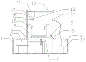
[0014] see figure 1 , a simple metal tube polishing equipment, including a base 1, a drive motor 2 is provided at the bottom of the inner cavity of the base 1, and the drive motor 2 can realize the slow and automatic forward movement of the movable plate 5, and the drive motor 2 is a There is a dust removal chamber 3 on the side, which effectively absorbs the smoke and dust generated during the processing and protects the environment. The top en...


PUM


Abstract

The invention relates to simple metal tube polishing equipment. The simple metal tube polishing equipment comprises a base. A driving motor is arranged at the bottom of an inner chamber of the base. A dedusting chamber is formed in one side of the driving motor. One end of the top of the base is connected with a movable plate through a sliding groove. A support frame is arranged at the two sides of the movable plate. The driving motor is connected with the bottom of the movable plate through a gear. A concave slide rail is arranged at the top of the movable plate. The two ends of the top of the concave slide rail are each connected with a movable platform. A tightening bolt is connected between the movable platforms. One side of the support frame is connected with a screw rod. One side of the screw rod is connected with a hydraulic component. The bottom of the hydraulic component is connected with a grinding wheel through a hydraulic rod. A distance sensor is arranged at one side of the hydraulic component. By means of the simple metal tube polishing equipment, the requirement of conducting polishing operation on different metal tubes can be met, and in addition, polishing is conducted uniformly; unidirectional automatic polishing operation is implemented; in addition, environmental pollution caused by smoke and dust generated by polishing operation is effectively prevented; and the simple metal tube polishing equipment is high in work efficiency and reasonable in design.

Description

technical field [0001] The invention relates to a simple metal tube polishing equipment, which belongs to the technical field of drying equipment. Background technique [0002] In the terminal building of the airport, the waiting hall of the bus station, the railway station, etc., the handrails on the subway, metal slender tubes can be seen everywhere, and they can be found everywhere in daily life. People have a great demand for this metal tube Increase, after the metal pipe is processed and formed, the surface will be rough and there are many barbs, which will not only affect the appearance but also accelerate the rusting. The surface of the metal pipe will be damaged or rusted during storage. It is necessary to use a grinder to grind the surface The damage or rust is polished to make the surface of the metal pipe smooth and flat. However, part of the polishing of the metal pipe with a grinder is a manual operation, which takes a lot of time, and the work efficiency is low...

Claims


Application Information

Patent Timeline
Patent Type & Authority Applications(China)
IPC IPC(8): B24B5/04B24B5/35B24B5/36B24B27/033B24B41/02B24B41/06B24B55/06
CPCB24B5/04B24B5/35B24B5/36B24B27/033B24B41/02B24B41/067B24B55/06
Inventor 蒋伟
Owner 张家港市华扬冶金机械有限公司
Why Eureka
Try Eureka