Vehicle clutch pedal mechanism and vehicle comprising same

A clutch pedal, clutch pedal technology, applied in vehicle components, control devices, transportation and packaging, etc., can solve the problems of increased clutch pedal stroke, affecting clutch pedal performance, incomplete clutch separation, etc., to shorten the distance, easy to discharge , the effect of stable performance

Inactive Publication Date: 2017-01-11
GREAT WALL MOTOR CO LTD
View PDF11 Cites 6 Cited by
  • Summary
  • Abstract
  • Description
  • Claims
  • Application Information

AI Technical Summary

Problems solved by technology

Further, the end where the oil outlet of the clutch master cylinder is located is slightly inclined upward. When the liquid in the clutch master cylinder generates gas due to temperature or pressure changes, the gas is not easily discharged from the oil inlet of the clutch master cylinder, which makes the clutch pedal The stroke increases and the separation stroke shortens, which affects the performance of the clutch pedal, and the phenomenon of incomplete separation of the clutch occurs, and there is room for improvement

Method used


Image

  • Vehicle clutch pedal mechanism and vehicle comprising same
  • Vehicle clutch pedal mechanism and vehicle comprising same
  • Vehicle clutch pedal mechanism and vehicle comprising same

Examples


Embodiment Construction

[0032] It should be noted that, in the case of no conflict, the embodiments of the present invention and the features in the embodiments can be combined with each other.

[0033] The present invention will be described in detail below with reference to the accompanying drawings and examples.

[0034] First, a clutch pedal mechanism 100 for a vehicle according to an embodiment of the present invention will be described in detail with reference to the drawings.

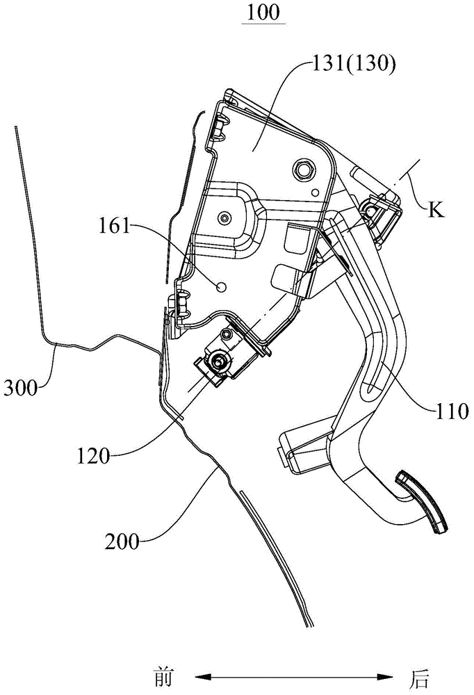
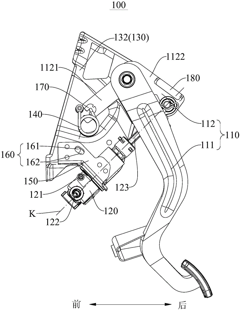
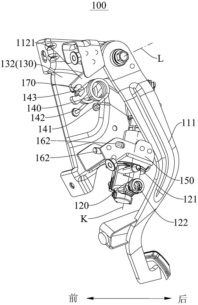
[0035] like Figure 1-Figure 5 As shown, the clutch pedal mechanism 100 includes a clutch pedal 110 and a clutch master cylinder 120 . Wherein, the clutch pedal 110 can rotate around the axis (such as image 3 Line L) in the rotation, the piston rod 123 of the clutch master cylinder 120 is connected with the clutch pedal 110 to move along the axis of the clutch master cylinder 120 when the clutch pedal 110 is stepped on (such as Figure 1-Figure 3 Line K in ).

[0036] That is to say, when the clutch pedal 110 is st...


PUM


Abstract

The invention provides a vehicle clutch pedal mechanism and a vehicle comprising the same. The vehicle clutch pedal mechanism comprises a clutch pedal and a clutch master cylinder, wherein the clutch pedal can rotate around the rotating axis; an oil inlet of the clutch master cylinder is located above an oil outlet of the clutch master cylinder; and a piston rod of the clutch master cylinder is connected with the clutch pedal so that the piston rod can move along the axis of the clutch master cylinder when the clutch pedal is treaded. According to the vehicle clutch pedal mechanism, gas in the clutch master cylinder is easy to exhaust, and the performance of the clutch pedal mechanism is more stable.

Description

technical field [0001] The invention relates to the technical field of vehicle manufacturing, in particular to a clutch pedal mechanism of a vehicle and a vehicle with the clutch pedal mechanism. Background technique [0002] The clutch pedal mechanisms of existing vehicles mostly make the clutch master cylinder run through the dash panel of the vehicle, that is, part of the clutch master cylinder is located between the dash panel and the shock absorber support of the vehicle, which makes the shock absorber support and the dash The distance between the plates is required to be large, which compresses the cabin space of the vehicle. Further, the end where the oil outlet of the clutch master cylinder is located is slightly inclined upward. When the liquid in the clutch master cylinder generates gas due to temperature or pressure changes, the gas is not easily discharged from the oil inlet of the clutch master cylinder, which makes the clutch pedal The stroke increases and the...

Claims


Application Information

Patent Timeline
Patent Type & Authority Applications(China)
IPC IPC(8): B60K23/02
Inventor 马显朱云袁东薛志海蔡礼刚赵永刚辛子超李成诚李麒
Owner GREAT WALL MOTOR CO LTD
Why Eureka
Try Eureka