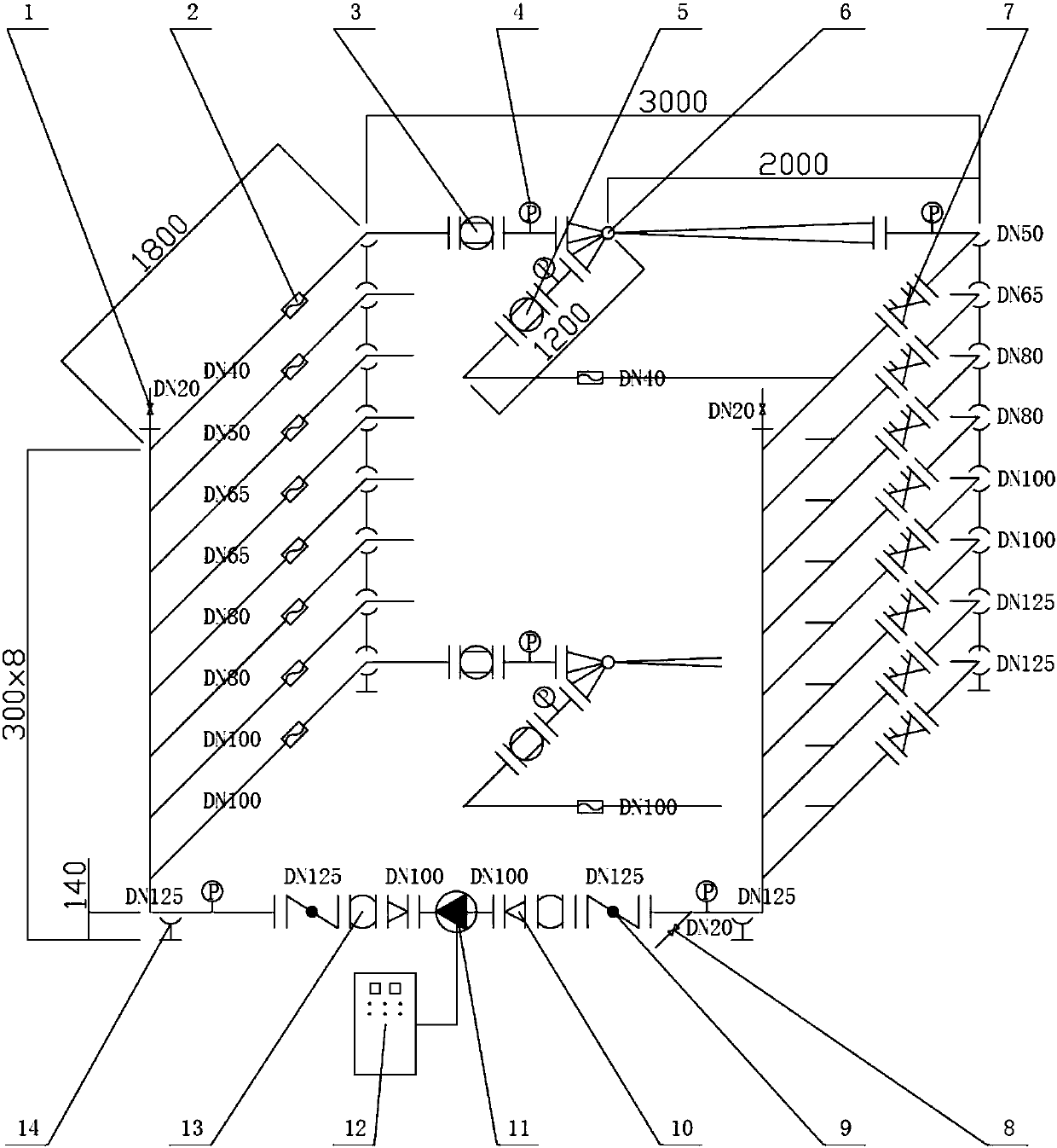
Jet pump test bench for heating

A technology of jet pump and test bench, which is applied in the field of jet pump for heat supply and jet pump heating system

Active Publication Date: 2018-04-10
北京顺欣兴盛机械钢筋连接技术有限公司
View PDF6 Cites 0 Cited by
  • Summary
  • Abstract
  • Description
  • Claims
  • Application Information

AI Technical Summary

Problems solved by technology

[0004] The purpose of the present invention is to provide a jet pump test bench for heat supply, to solve the problem that through the simulation experiment of the test bench, the characteristic equation of the jet pump for heat supply can be summarized, and the design theory of the jet pump heat supply system can be perfected, so as to provide a good solution for the heat supply. Issues such as laying a solid foundation for the establishment of jet pump industry standards

Method used


Image

  • Jet pump test bench for heating

Examples


Embodiment Construction

[0012] A jet pump test bench for heating, including an exhaust valve, an ultrasonic flowmeter, a jet ball valve, a digital pressure gauge, an injection ball valve, a jet pump for heating, a regulating balance valve, a water replenishing valve, a butterfly valve, a reducing pipe, and a circulation Pumps, frequency conversion control cabinets, flexible connecting pipes, brackets, etc.

[0013] Multiple jet pumps for heating are installed in parallel, with different models; each jet pump for heating has a jet ball valve, an injection ball valve, and a regulating balance valve connected to it, and its operating pressure can be directly controlled by the digital pressure gauge in between. Readout: The flow through the injection ball valve and injection ball valve of each heating injection pump can be directly measured by the ultrasonic flowmeter on it.

[0014] The following examples are used to illustrate the present invention, but are not intended to limit the scope of the presen...


PUM


Abstract

The invention discloses a test bed for heating injection pumps. A single heating injection pump or a unit of heating injection pumps in parallel connection is connected between the high-pressure end the low-pressure end of a pipe network pressure difference part. On the branch where each heating injection pump is located, the front end of the heating injection pump is connected with an ultrasonic flow meter and a jet ball valve. A digital pressure gauge is installed at the rear end of the jet ball valve. The rear end of the heating injection pump is connected in series with adjustment balance valves of which once pipe network resistance in the simulated heat user building or the heat transfer station is changed by opening, a pressure gauge is installed at the front end of the adjustment balance valves, and the rear end of the balance valves are connected with the other input ends of the heating injection pumps through the jet ball valves. The test bed can solve the problems that by the simulation experiment of the test bed, the design equation of the heating injection pump can be summarized, the design theory of the heating system of the injection pump can be improved, and a solid foundation for the development of the heating injection pump industry standard can be established.

Description

technical field [0001] The invention relates to a jet pump for heat supply and a jet pump heat supply system. Background technique [0002] The jet pump heating system has high hydraulic stability and can solve the hydraulic imbalance problem of the existing heating system. The general heat saving rate is 10-30%, and the electricity saving rate is 20-50%. [0003] However, the hydraulic characteristics of jet pumps for heating are not clear at present, and the design theory of jet pumps for heating is not perfect. Therefore, there is no industry standard for jet pumps for heating in my country. Contents of the invention [0004] The purpose of the present invention is to provide a jet pump test bench for heat supply, to solve the problem that through the simulation experiment of the test bench, the characteristic equation of the jet pump for heat supply can be summarized, and the design theory of the jet pump heat supply system can be perfected, so as to provide a good sol...

Claims


Application Information

Patent Timeline
Patent Type & Authority Patents(China)
IPC IPC(8): F04B51/00
CPCF04B51/00
Inventor 曾喜平杨小军刘宝华
Owner 北京顺欣兴盛机械钢筋连接技术有限公司
Why Eureka
Try Eureka