rear shock absorber ring
A technology for shock absorbers and rings, applied to springs/shock absorbers, springs made of plastic materials, mechanical equipment, etc., can solve problems such as inconvenient installation and disassembly, poor grip of shock absorber rings, etc. Convenience, easy installation and disassembly, good comfort effect
- Summary
- Abstract
- Description
- Claims
- Application Information
AI Technical Summary
Problems solved by technology
Method used
Image

Examples
Embodiment 1
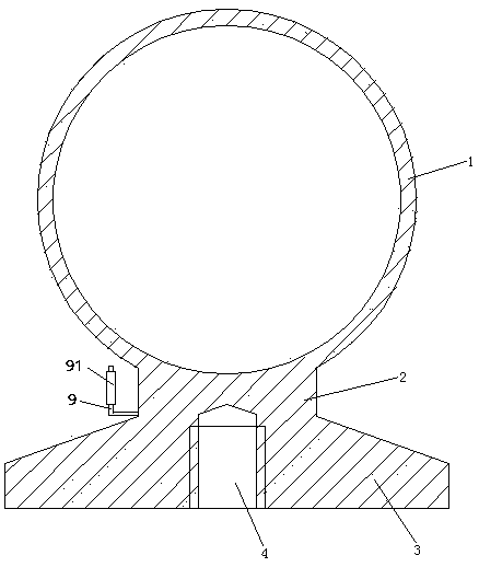
[0027] Embodiment one, see figure 1 , a rear shock absorber suspension ring, including a connecting ring 1, a connecting neck 2 and a connecting seat 3. The connecting ring 1 is connected to one end of the connecting neck 2 in a structural manner. The cross section of the connecting neck 2 is rectangular, so in this embodiment, the connecting neck 2 has two pairs of parallel surfaces (one pair is the front and rear surfaces, and the other end is the upper and lower surfaces). The connecting base 3 is connected to the other end of the connecting neck 2 in an integral structure. The connection seat 3 is disc-shaped. A threaded hole 4 is provided at the end of the connecting base 3 away from the connecting ring. The threaded hole 4 penetrates into the connecting neck 2 .
[0028] A handle bar 9 is provided at the connecting neck 2 . The outer elastic sleeve of the handle bar 9 is provided with a sleeve 91 .
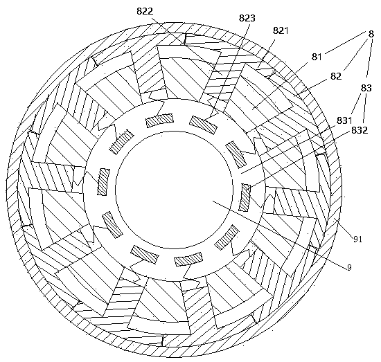
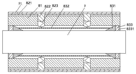
[0029] see figure 2, An elastic adjustment mechanism 8 is provi...
Embodiment 2
[0033] Embodiment two, the difference with embodiment one is:
[0034] see Figure 4 , the connecting ring 1 is pierced with an inner ring 5 . The inner ring 5 is a steel structure. The inner ring 5 is connected with the connecting ring 1 through the rubber ring 7 .
[0035] The inner peripheral surface of the rubber ring 7 is provided with several blind holes 71 distributed along the circumferential direction of the rubber ring (it is also possible for the blind holes to be arranged on the outer peripheral surface of the rubber ring). An isolation plate 72 is disposed in the blind hole 71 . The isolation plate 72 divides the blind hole 71 into two cavities, namely an inner cavity 711 and an outer cavity 712 . The open end of the blind hole 71 is covered with an elastic cover 73 . The elastic cover 73 is in the shape of a bowl arched towards the inside of the blind hole 71 .
[0036] see Figure 5 , The isolation plate 72 is provided with several main friction channels ...
Embodiment 3
[0040] Embodiment three, the difference with embodiment two is;
[0041] see Figure 8 , also includes the driving mechanism 6. The inner ring 5 is rotatably connected to the rubber ring 7 , and the rubber ring 7 is fixedly connected with the connecting ring 1 .
[0042] The drive mechanism 6 includes a ratchet 61 , a pawl 62 for driving the ratchet, and a drive lever 63 . The ratchet 61 is coaxially connected with the inner ring 5 . The ratchet 61 is integrally structured with the inner ring 5 . The pawl 62 is fixedly connected to one end of the driving rod 63 . The connecting seat 3 is provided with a sliding hole 31 . The other end of the driving rod 63 can slide two-dimensionally through the sliding hole 31 . The driving rod 63 is provided with a storage hole 64 . There are two storage holes 64 . An engagement spring 65 passes through the storage hole 64 . The engagement spring 65 is a tension spring. One end of the engaging spring 65 is connected together with t...
PUM
 Abstract
Description
Claims
Application Information