Power converter

A power converter and circuit technology, applied in the direction of output power conversion device, DC power input conversion to DC power output, instruments, etc., can solve the problems of limited power, complex circuit, single-stage isolation converter is difficult to meet the demand, etc. Achieve high power density and high efficiency

Active Publication Date: 2017-01-11
DELTA ELECTRONICS INC
View PDF6 Cites 19 Cited by
  • Summary
  • Abstract
  • Description
  • Claims
  • Application Information

AI Technical Summary

Problems solved by technology

In addition, the circuit of a single-stage isolation converter with a 48V input voltage is relatively complicated, and the single-stage isolation converter with a 48V input voltage directly supplies power to a single load, which means that the power is limited, and it is not suitable for parallel multiplexing to reduce the volume of the capacitor. Light-load efficiency improvement and other functions
Therefore, a single-stage isolated converter with 48V input voltage is difficult to meet the needs of future development

Method used


Image

  • Power converter
  • Power converter
  • Power converter

Examples


Embodiment 1

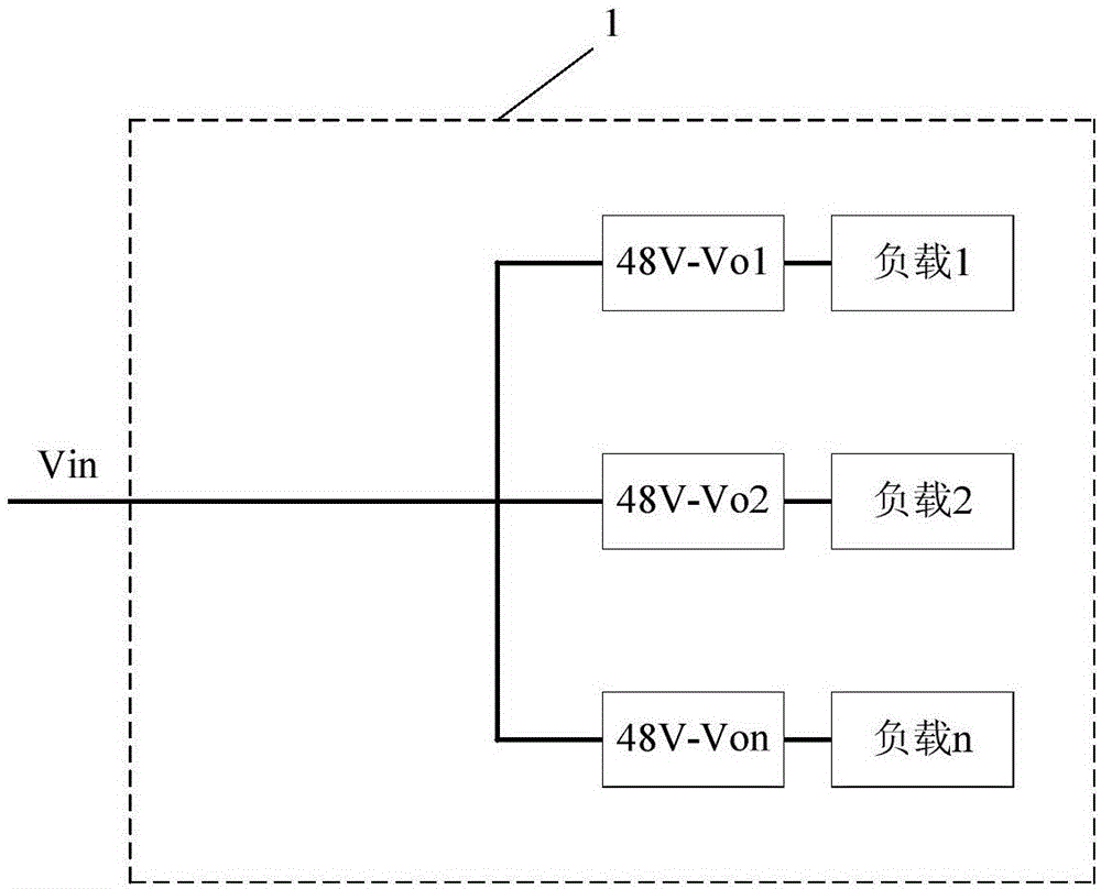
[0054] This embodiment provides a power converter. The power converter includes two stages of circuits, namely a front-stage circuit and a rear-stage circuit. The front-stage circuit is used to receive an input voltage and convert the received input voltage into a bus voltage Output the bus voltage; the latter circuit can be multiple, connected in parallel to the output end of the previous circuit, used to receive the bus voltage output by the previous circuit, and convert the bus voltage into an output voltage respectively, and supply the connection It is used for the load at the output end of the post-stage circuit.

[0055] Next, the power converter of this embodiment will be described with reference to specific examples.

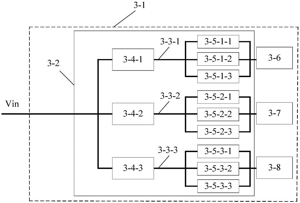
[0056] Figure 3A A schematic structural diagram of the power converter provided by this embodiment is shown, as Figure 3A As shown, the power converter 3-2 includes multiple pre-stage circuits and multiple post-stage circuits. The input ends of the ...

Embodiment 2

[0072] Figure 7 shows the package structure diagram of the power converter, in Figure 7 The front stage circuit (taking the LLC circuit as an example) 7-2 and the rear stage circuit (taking the BUCK circuit as an example) 7-3 are packaged in independent modules respectively, and are carried on the data processing main board 7-1. The motherboard 7-1 also carries a CPU 7-6 and a radiator 7-7, wherein the radiator 7-7 is used to dissipate heat for the CPU 7-6, and the power converter is used to provide power to the CPU 7-6. The front-stage circuit 7-2 includes an output capacitor 7-4, and the rear-stage circuit 7-3 includes an input capacitor 7-5. The front and back stage circuits are respectively located in their own packaging modules, forming two independent components. In practical applications, the distance between the output capacitor 7-4 of the previous stage circuit and the input capacitor 7-5 of the subsequent stage circuit is relatively long, and there is a relativel...


PUM


Abstract

The invention provides a power converter. The power converter comprises multiple preceding-stage circuits and multiple backward-stage circuits, wherein the preceding-stage circuits receive an input voltage and convert the input voltage into bus voltages separately; the multiple backward-stage circuits are connected to the output ends of the preceding-stage circuits in parallel respectively for receiving the bus voltages from the preceding-stage circuits, and converting first bus voltages into output voltages separately. By adoption of the power converter provided by the invention, the problem of a wide range of isolating and operating voltages can be effectively solved; and meanwhile, high efficiency ad high power density can be achieved at the same time.

Description

technical field [0001] The invention relates to the technical field of power modules, in particular to a power converter. Background technique [0002] With the improvement of human's requirements for intelligent life, the society's demand for data processing is increasingly strong. The global energy consumption in data processing reaches hundreds of billions or even trillions of kWh per year on average; and the floor area of ​​a large data center can reach tens of thousands of square meters. Therefore, high efficiency and high power density are key indicators for the healthy development of this data center industry. [0003] The key unit of the data center is the server, and its motherboard is usually composed of data processing chips such as CPU, chipset (Chipsets), memory, etc., their power supply and necessary peripheral components. With the improvement of server processing capacity per unit volume, it means that the number and integration of these processing chips are...

Claims


Application Information

Patent Timeline
Patent Type & Authority Applications(China)
IPC IPC(8): H02M3/335H02M3/07
CPCH02M3/33592H02M1/14Y02B70/10H02M1/0048H02M1/008H02M3/33571H02J5/00
Inventor 曾剑鸿忽培青叶浩屹陈燕代佳乐周子颖
Owner DELTA ELECTRONICS INC
Why Eureka
Try Eureka