Automobile exhaust waste heat thermoelectric generator device adopting phase change materials
A phase change material, automobile exhaust technology, applied in exhaust devices, mufflers, generators/motors, etc., can solve the problems of exhaust pipe temperature changes, welding, the thermoelectric generator cannot work normally, etc., to achieve extended operation. longevity, improved performance, and the effect of
- Summary
- Abstract
- Description
- Claims
- Application Information
AI Technical Summary
Problems solved by technology
Method used
Image

Examples
Embodiment Construction
[0014] In order to further understand the invention content, characteristics and effects of the present invention, the following examples are given, and detailed descriptions are as follows in conjunction with the accompanying drawings:
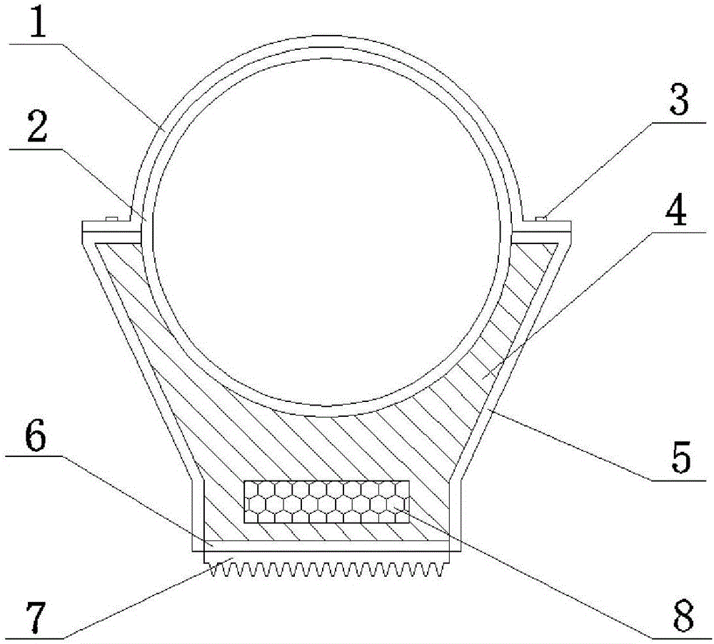
[0015] see figure 1 , an automobile exhaust waste heat thermoelectric power generation device using phase change materials, comprising a thermal conductor 4 bonded and fixed on the exhaust pipe 2, a thermoelectric generator 6 is fixed on the thermal conductor 4, and the thermoelectric generator 6 The hot end of the heat conductor is attached to the outer surface of the heat conductor 4, a radiator 7 is provided at the cold end of the thermoelectric generator 6, and a corresponding The chamber of the phase change material is filled with the phase change material 8 .
[0016] If the structure of the phase change material containing cavity is not proper, the temperature distribution at the hot end of the thermoelectric generator may be uneven; ...
PUM
 Abstract
Description
Claims
Application Information