
Video monitoring terminal

A video monitoring and terminal technology, which is applied in the field of video monitoring terminals, can solve the problems of poor redundancy of video monitoring terminals, etc., and achieve the effects of flexible and convenient current ratio control, strong power supply stability, and stable total current

Pending Publication Date: 2017-01-11
XINZHOU POWER SUPPLY COMPANY STATE GRID SHANXI ELECTRIC POWER
View PDF6 Cites 0 Cited by
  • Summary
  • Abstract
  • Description
  • Claims
  • Application Information

AI Technical Summary

Problems solved by technology

[0004] The invention solves the problem of poor redundancy of existing video monitoring terminals, and provides a video monitoring terminal capable of effectively storing video image data for a long time

Method used


Image

  • Video monitoring terminal
  • Video monitoring terminal
  • Video monitoring terminal

Examples


Embodiment Construction

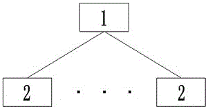
[0018] A video monitoring system, which is composed of a video monitoring center server 1 and a plurality of video monitoring terminals 2 installed at video monitoring points, each video monitoring terminal 2 is connected to the video monitoring center server 1 through an optical fiber communication network for communication;

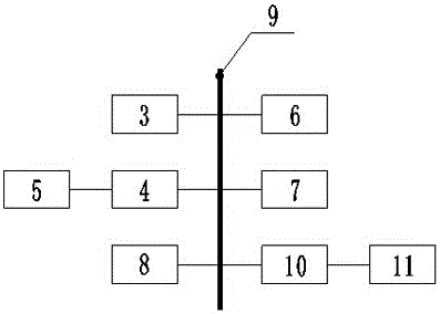
[0019] Video surveillance center server 1 includes administrator computer 3, DMR digital matrix 4, large-screen display 5, media server 6, playback server 7 and optical fiber router 8, administrator computer 3, DMR digital matrix 4, media server 6, playback server 7 It communicates with the optical fiber router 8 through the optical fiber private network 9, and the large-screen display 5 is electrically connected with the DMR digital matrix 4 for communication;

[0020] The video monitoring center server 1 also includes a switch 10, which is connected to the optical fiber private network 9, and the video monitoring center server 1 communicates with the s...


PUM


Abstract

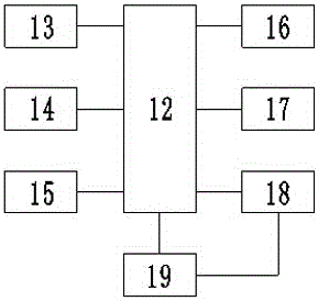
The invention relates to a video monitoring terminal, in particular to a video monitoring terminal which can effectively store video image data for a long term and solve the problem of poor redundancy of an existing video monitoring terminal. The video monitoring terminal comprises a main control module, a fiber optical transceiver, a storage module, an anti-theft alarm module, a clock module, a reset control module, a high-definition camera and a power module, wherein the main control module is respectively connected with the fiber optical transceiver, the storage module, the anti-theft alarm module, the clock module, the reset control module, the high-definition camera and the power module to perform communication, and the high-definition camera is electrically connected with the power module. The resolution ratio of a shot video is ensured by the aid of the high-definition camera, authenticity and real-time transmission of the video are ensured by the aid of the anti-theft alarm module and fiber optical communication technology, system power supply is ensured by the aid of a dual power supply system, power supply redundancy of the system is improved, and video shooting continuity is ensured.

Description

technical field [0001] The invention relates to a video monitoring system, in particular to a video monitoring terminal in the video monitoring system, in particular to a video monitoring terminal capable of effectively storing video image data for a long time. Background technique [0002] With the rapid development of the national economy and the rapid development of information technology and network technology, the application of monitoring systems in various industries is becoming more and more extensive. Monitoring systems are not only used in communication, transportation, security and other industries. It is gradually developing towards other industries and the public. With the rapid development of computer, network, image processing and transmission technology, video surveillance technology has also made great progress. The social security situation is becoming more and more complicated, public safety issues are constantly highlighted, urban crimes are prominent, a...

Claims


Application Information

Patent Timeline
Patent Type & Authority Applications(China)
IPC IPC(8): H04N7/18H04N7/22H04N7/015H02J1/10
CPCH02J1/10H04N7/015H04N7/181H04N7/22
Inventor 张慧峰王改香
Owner XINZHOU POWER SUPPLY COMPANY STATE GRID SHANXI ELECTRIC POWER
Learn More