
Nozzle calibration method of 3D printer

A technology of a 3D printer and a calibration method, which is applied in the field of 3D printing, can solve problems such as large calibration errors affecting printing efficiency, affecting printing efficiency and printing quality, and operating experience limitations, so as to improve practicability and applicability, improve printing quality and The success rate and the effect of solving the limitation of operation experience

Active Publication Date: 2017-01-18
WUXI TIERTIME TECH CO LTD
View PDF3 Cites 10 Cited by
  • Summary
  • Abstract
  • Description
  • Claims
  • Application Information

AI Technical Summary

Problems solved by technology

[0005] The purpose of the present invention is to provide a method for calibrating nozzles of 3D printers, which has the advantages of simple operation, precise calibration, and high degree of automation, and can effectively solve the problems of existing nozzle calibration methods that are limited by operating experience and have large calibration errors that affect printing efficiency. problems, to ensure the print quality and success rate
[0006] In order to solve the problem of manual calibration combined with software calibration in the prior art, which is affected by personal operating experience, the calibration is not accurate and needs to be corrected by error values, thus affecting the printing efficiency and printing quality. The present invention provides a 3D printer nozzle A calibration method comprising the steps of:

Method used


Image

  • Nozzle calibration method of 3D printer
  • Nozzle calibration method of 3D printer

Examples


specific Embodiment approach

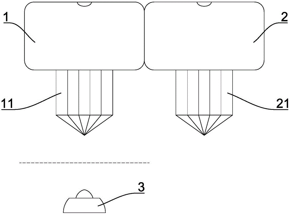
[0029] Such as figure 1 with figure 2 Shown is a specific implementation of a 3D printer nozzle calibration method of the present invention, which mainly includes the following steps:

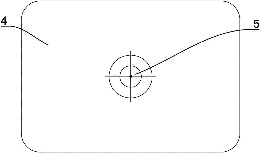
[0030] 1. Establish a calibration area, and set up a camera with a vertical optical axis and facing up in the calibration area; connect the camera to the control system of the 3D printer;

[0031] 2. Establish a real-time display window corresponding to the calibration area in the control system;

[0032] 3. The nozzle composed of the main nozzle and the auxiliary nozzle is moved to the top of the calibration area through the control of the control system;

[0033] 4. Move the nozzle as a whole in the x-y plane of the calibration area, and observe through the real-time display window to obtain the position of the main nozzle and the auxiliary nozzle, determine the relative distance between the two according to the position of the main nozzle and the auxiliary nozzle, record is (△x,△y);

[...


PUM


Abstract

The invention discloses a nozzle calibration method of a 3D printer. The method comprises steps as follows: a calibration zone is established, and a camera with a perpendicular and upward optical axis is arranged in the calibration zone; the camera is connected with a control system of the 3D printer; a real-time display window corresponding to the calibration zone is established in the control system; a nozzle comprising a main nozzle and an auxiliary nozzle is integrally moved above the calibration zone; the nozzle is integrally moved in an x-y plane of the calibration zone and is observed through the real-time display window, the position of the main nozzle and the position of the auxiliary nozzle are acquired, and the relative distance between the main nozzle and the auxiliary nozzle is determined according to the position of the main nozzle and the position of the auxiliary nozzle and is recorded as (deltax, deltay); (deltax, deltay) is fed back to the control system and is used as a compensation parameter for the distance between the main nozzle and the auxiliary nozzle. The method has the advantages of being simple to operate, accurate in calibration and high in automation degree, and the problems that the printing quality and efficiency are affected due to large calibration errors caused by the fact that existing nozzle calibration manners are limited by operation experience are solved.

Description

technical field [0001] The invention relates to the technical field of 3D printing, in particular to a nozzle calibration method of a 3D printer. Background technique [0002] 3D printing technology (that is, rapid prototyping technology) has developed rapidly because of its many advantages over the existing subtractive processing technology. With the development of technology, those skilled in the art have researched and developed various types of dual-nozzle and multi-nozzle 3D printers to achieve dual / multi-color printing, or itemized printing of special support materials and model materials. [0003] For the dual-nozzle 3D printer, because the dual-nozzle structure is installed and fixed on the same motion axis, and they move and work together during the printing process, there are problems of mutual interference and mutual restriction. When the main nozzle prints, the auxiliary nozzle is in a pause state and performs cooling processing, and when the auxiliary nozzle pr...

Claims


Application Information

Patent Timeline
Patent Type & Authority Applications(China)
IPC IPC(8): B29C67/00B33Y10/00B33Y40/00
CPCB33Y10/00B33Y40/00
Inventor 唐果林郭戈王铁卓高明希
Owner WUXI TIERTIME TECH CO LTD
Learn More