Time domain aero-electromagnetic data inversion method based on conductivity-depth imaging

An airborne electromagnetic and data inversion technology, applied in the field of data inversion, can solve the problems of low accuracy of fast imaging method and difficult selection of initial model of inversion method, and achieve fast and stable inversion method, high convergence rate and imaging accuracy. , the effect of solving difficult choices

Inactive Publication Date: 2017-01-18
CHENGDU UNIVERSITY OF TECHNOLOGY
View PDF0 Cites 17 Cited by
  • Summary
  • Abstract
  • Description
  • Claims
  • Application Information

AI Technical Summary

Problems solved by technology

[0006] The purpose of the present invention is to provide a time-domain airborne electromagnetic data inversion method based on conductivity-depth im

Method used


Image

  • Time domain aero-electromagnetic data inversion method based on conductivity-depth imaging
  • Time domain aero-electromagnetic data inversion method based on conductivity-depth imaging
  • Time domain aero-electromagnetic data inversion method based on conductivity-depth imaging

Examples


Embodiment 1

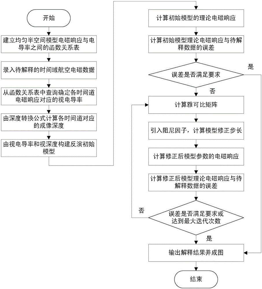
[0028] The workflow of the present invention is as figure 1 shown, including the following steps:

[0029] (1) Assume that the time-domain aeronautical electromagnetic detection system maintains a stable flight state when the aircraft is flying, the coil maintains a horizontal state during the flight, and the coil height is 30m. Using the central loop source time-domain airborne electromagnetic one-dimensional forward modeling algorithm, calculate the conductivity of the uniform half-space geoelectric model in the range of 0.0001S / m-100S / m and the vertical direction two of 26 time channels within 10ms after power failure Secondary field electromagnetic response value, according to the electrical conductivity and electromagnetic response value to establish a functional relationship table between the electromagnetic response and electrical conductivity;

[0030] (2) Substitute the one-dimensional forward modeling electromagnetic response simulation data of the three-layer H-typ...

Embodiment 2

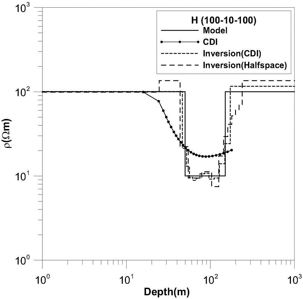
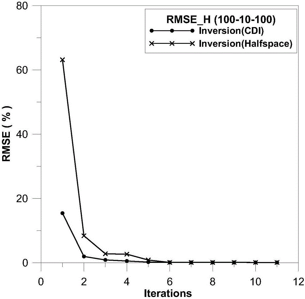
[0049] The steps of this embodiment are basically the same as those of Embodiment 1, except that the one-dimensional forward modeling electromagnetic response simulation data of the three-layer H-type geoelectric model input in step (2) of Embodiment 1 is changed to that of the inclined low-resistivity layer geoelectric model. The one-dimensional forward modeling electromagnetic response data, the sampling time of the secondary field is consistent, the height of the transmitting coil is still 30m, and the geoelectric model of the inclined low-resistance layer is shown in the figure Figure 4 As shown, the resistivity of the middle inclined low-resistivity layer is 50Ω·m, and the resistivity of the surrounding rock is 500Ω·m.

[0050] The inversion result is shown in Fig. Figure 5 , 6 , as shown in 7, Figure 5 is the conductivity-depth imaging result map, Figure 6 is the inversion result map of the initial model constructed from the conductivity-depth imaging results, F...


PUM

PropertyMeasurementUnit
Heightaaaaaaaaaa
Resistivityaaaaaaaaaa

Abstract

The invention discloses a time domain aero-electromagnetic data inversion method based on conductivity-depth imaging. First, the apparent conductivity and apparent depth of an underground medium are obtained by use of a conductivity-depth imaging method based on a tale look-up method; then, an inversion initial model is built based on the apparent conductivity and the apparent depth; and finally, inversion is performed by use of a damping characteristic parameter method to complete combination analysis of time domain aero-electromagnetic data. The problem that it is difficult to choose an inversion initial model is solved. As inversion is performed on the basis of the result of approximate imaging, the inversion method has certain constraints of the inversion result, and inversion is of high convergence rate and imaging precision. The invention provides a quick and stable inversion method for time domain aero-electromagnetic data interpretation.

Description

technical field [0001] The invention relates to a data inversion method in the field of time-domain airborne electromagnetic method, in particular to a combined inversion method based on time-domain airborne electromagnetic data conductivity-depth imaging and damping characteristic parameters. Background technique [0002] The time-domain airborne electromagnetic method (ATEM) is an airborne geophysical exploration method based on the aircraft as the carrier and the theory of electromagnetic induction. It has the advantages of fast speed, low cost, large-scale exploration, and adaptability to complex terrain conditions. It has been widely used In the fields of mineral resource exploration, geological mapping, water resource exploration and environmental monitoring. However, the amount of data obtained by the time-domain airborne electromagnetic method is large, and the data interpretation is difficult. In recent years, some scholars have studied the 3D inversion of airborne...

Claims


Application Information

Patent Timeline
IPC IPC(8): G01V3/38
CPCG01V3/38
Inventor 陆从德王绪本余小东高嵩
Owner CHENGDU UNIVERSITY OF TECHNOLOGY
Why Eureka
Try Eureka