Supercharge Your Innovation With Domain-Expert AI Agents!

Display apparatus and display method

A technology of a display device and a display method, applied in static indicators, instruments, active addressing light modulators, etc., can solve the problem of inability to view holographic images on a holographic dry board

Active Publication Date: 2017-01-18
BOE TECH GRP CO LTD
View PDF6 Cites 10 Cited by
  • Summary
  • Abstract
  • Description
  • Claims
  • Application Information

AI Technical Summary

Problems solved by technology

[0003] The disadvantage of the existing technology is that the holographic dry plate records static images, and the dynamic holographic image cannot be viewed through the holographic dry plate

Method used


Image

  • Display apparatus and display method
  • Display apparatus and display method
  • Display apparatus and display method

Examples


Embodiment 1

[0056] This embodiment provides a display device, including:

[0057]An optical device, the optical device includes a plurality of mutually independent optical units, the optical unit can refract the incident linearly polarized laser light, the refractive index of the optical unit is adjustable, and the refractive index of the adjacent optical unit Change into a sinusoidal distribution;

[0058] A laser light source located on the light-incident side of the optical device, used to emit a laser beam corresponding to the holographic image to be displayed;

[0059] a drive circuit connected to the optical device;

[0060] a holographic image data storage unit connected to the drive circuit;

[0061] The driving circuit is used for acquiring image data of a holographic image to be displayed from the holographic image data storage unit, and adjusting the refractive index of each optical unit according to the image data.

[0062] In this embodiment, when displaying a holographic ...

Embodiment 2

[0078] This embodiment provides a display method, which is applied to the above-mentioned display device, and the display method includes:

[0079] Acquiring image data of the holographic image to be displayed;

[0080] The refractive index of each optical unit is adjusted according to the image data.

[0081] In this embodiment, when displaying a holographic image, the laser light source emits a laser beam corresponding to the holographic image to be displayed, and the optical unit can refract the incident linearly polarized laser light, and the refractive index of the optical unit is adjustable. The refractive index of the optical unit can make the optical path difference generated by the laser beam in the optical device equivalent to the optical path difference of the laser beam in the ordinary holographic dry plate, so that the display of the holographic image can be realized. At the same time, due to the refractive index of the optical unit Dynamic adjustment is possible...

Embodiment 3

[0090] The display device of the present invention is further introduced below in conjunction with the accompanying drawings:

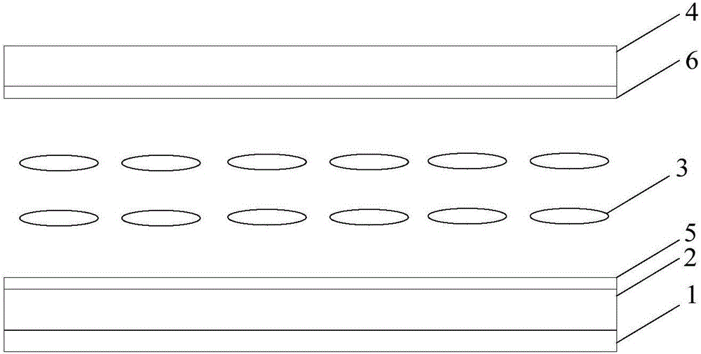
[0091] image 3 It is a schematic diagram of the structure of the optical device in the embodiment of the present invention. The optical device is composed of a plurality of mutually independent optical units. The optical unit can refract the incident linearly polarized laser light. The refractive index of the optical unit is adjustable, and the adjacent optical unit The refractive index changes into a sinusoidal distribution. Such as image 3 As shown, the optical device sequentially includes: a polarizer 1 , a base substrate 2 , a first electrode 5 , a liquid crystal cell 3 , a second electrode 6 , and a base substrate 4 .

[0092] The upper surface of the base substrate 2 is provided with a first electrode 5, and the lower surface of the base substrate 4 is provided with a second electrode 6, both of the first electrode 5 and the second electrode...


PUM


Abstract

The invention provides a display apparatus and a display method, which belong to the technical field of display. The display apparatus comprises an optical device comprising a plurality of mutually independent optical units capable of refracting incident linearly polarized laser light, the refractive index of the optical units being adjustable and the refractive index of the adjacent optical unit changing to sinusoidal curve distribution; a laser source arranged at the light incident side of the optical device to emit laser beams corresponding to a to-be-displayed holographic image; a driving circuit in connection with the optical device; and a holographic image data storing unit in connection with the driving circuit. The driving circuit is used to obtain the image data of the to-be-displayed holographic image from the holographic image data storing unit, and based on the image data, adjusts the refractive index of each optical unit. According to the technical schemes of the invention, it is possible to realize the dynamic display of a holographic image.

Description

technical field [0001] The present invention relates to the field of display technology, in particular to a display device and a display method thereof. Background technique [0002] The traditional holographic dry plate records the amplitude and phase information in the object beam in the form of the contrast and light and dark changes of the interference fringes, forming irregular interference fringes. After photosensitive holographic dry plate, the hologram obtained by developing, fixing and other processing is equivalent to a diffraction grating, and the thickness of the grating groove is related to the shape of the object to be photographed. When the reference beam is used to irradiate the holographic dry plate, the human eye can observe the holographic dry plate in the projected light, and then the reconstructed image with the same shape as the original can be observed. [0003] The disadvantage of the prior art is that the holographic dry plate records static images,...

Claims


Application Information

Patent Timeline
IPC IPC(8): G03H1/22G02F1/1335G02F1/1333
CPCG02F1/1333G02F1/1335G02F1/133528G03H1/22G03H1/2294G03H2225/22G02F1/1343G09G3/36G09G2300/0478
Inventor 高健陈小川杨亚锋张粲王维孟宪芹王灿卢鹏程王倩
Owner BOE TECH GRP CO LTD
Features
  • R&D
  • Intellectual Property
  • Life Sciences
  • Materials
  • Tech Scout
  • Unparalleled Data Quality
  • Higher Quality Content
  • 60% Fewer Hallucinations
Learn More