Switchgear interlocking mechanism and switchgear

A switchgear and interlocking technology, applied in the field of electric power, can solve the problems of long service life, high material consumption, and high cost of switchgear, and achieve the effects of easy maintenance, easy assembly, and easy processing

Active Publication Date: 2017-01-18
莱福士电力电子设备(深圳)有限公司
View PDF6 Cites 5 Cited by
  • Summary
  • Abstract
  • Description
  • Claims
  • Application Information

AI Technical Summary

Problems solved by technology

Most of the interlocking mechanisms in the prior art use electromagnetic interlocking mechanisms with complex structures. Due to the long service life of the switchgear, the internal coils and circuits are prone to aging and failure, which makes the service life of the electromagnet interlocking mechanisms shorter. , low reliability
The structure of the existing mechanical lower door interlocking mechanism is relatively complex, there are many parts to be processed, more materials are consumed, and the cost is high

Method used


Image

  • Switchgear interlocking mechanism and switchgear
  • Switchgear interlocking mechanism and switchgear
  • Switchgear interlocking mechanism and switchgear

Examples


Embodiment Construction

[0029] In order to make the object, technical solution and advantages of the present invention more clear, the present invention will be further described in detail below in conjunction with the accompanying drawings and embodiments. It should be understood that the specific embodiments described here are only used to explain the present invention, not to limit the present invention.

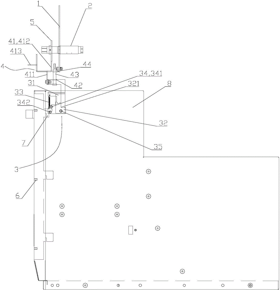
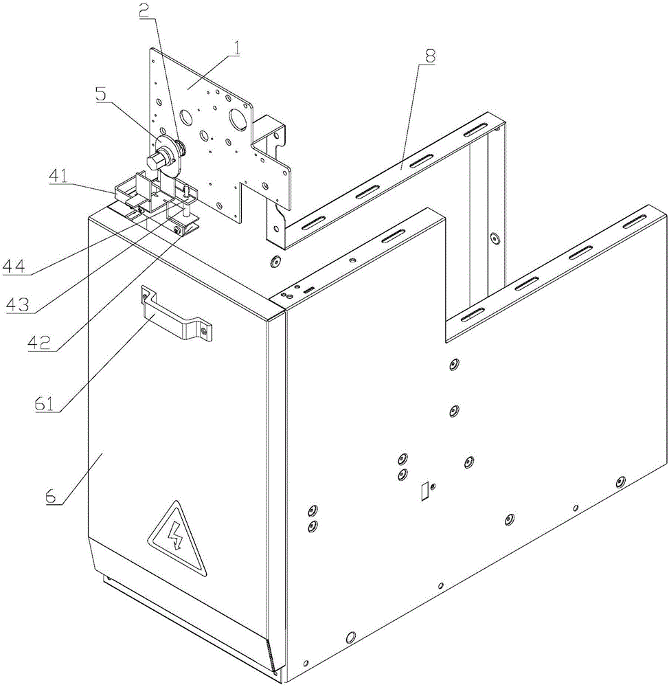
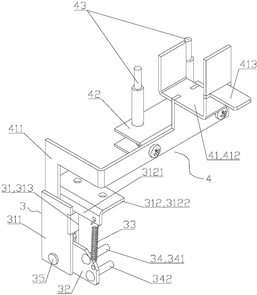
[0030] Such as Figure 1-3 As shown, the switch cabinet door interlock mechanism provided by the embodiment of the present invention includes an isolation front plate 1 installed in the switch cabinet and a grounding operation shaft 2 arranged on the isolation front plate 1. The grounding operation shaft 2 can be positioned relative to the isolation front plate. 1 rotation, the grounding operation shaft 2 rotates to enable the grounding switch to open or close; at the same time, a first interlocking device 3, a second interlocking device 4 and a limit plate 5 are provided; wherein, the first int...


PUM


Abstract

The invention discloses a switchgear door interlocking mechanism which comprises a front isolation board, a grounding operation shaft which rotates relative to the front isolation board, a first interlocking device having a locking state and an unlocking state, a second interlocking device movably arranged on the front isolation board, and a limiting plate arranged on the grounding operation shaft, when the grounding switch opens, the limiting plate abuts against the second interlocking device to limit the first interlocking device to the locking state, and when the grounding switch closes, the second interlocking device moves upward to allow the first interlocking device to be in an unlocking state. The switchgear comprises the switchgear door interlocking mechanism. Rotation of the grounding operation shaft drives the grounding switch to open and close, and the limiting plate also rotates. When the grounding switch opens, the first interlocking device is under the locking state, and the door can not be opened. When the grounding switch closes, the first interlocking device is under the unlocking state, and the door can be opened. The switchgear door interlocking mechanism and the switchgear have the advantages of simple structure, easy processing, assembly and operation, lower cost, reliable interlocking and maintenance convenience.

Description

technical field [0001] The invention belongs to the technical field of electric power, and in particular relates to a switch cabinet interlocking mechanism and a switch cabinet. Background technique [0002] Switch cabinets are used in switching stations of power plants, substations of transmission lines, and user terminal substations for receiving electric energy. In addition to circuit breakers, there are disconnectors, grounding switches, transformers, lightning arresters and secondary circuits in the switchgear. Since the switchgear is a high-voltage power distribution device, its safety level is relatively high. In order to ensure the personal safety of the operators and the normal operation of the cabinet, the basic requirement for the switchgear is that the grounding switch must be grounded when the switchgear is in the maintenance state to ensure the safety of the maintenance personnel; The lower door of the switch cabinet is allowed to be opened, that is, the isol...

Claims


Application Information

Patent Timeline
Patent Type & Authority Applications(China)
IPC IPC(8): H02B11/133
CPCH02B11/133
Inventor 陈波王景阳朱刚宁姚飞
Owner 莱福士电力电子设备(深圳)有限公司
Why Eureka
Try Eureka