Field fuel delivery vehicle
A technology for operating vehicles and oil materials, which is applied in the field of field oil sending and receiving operations, can solve the problems of cumbersome refueling operation process, lack of automation, and high manual work intensity, so as to overcome the cumbersome and laborious process of oil distribution, reduce labor intensity, and improve support capabilities Effect
Inactive Publication Date: 2010-12-15
中国人民解放军北京军区油料训练大队
View PDF0 Cites 1 Cited by
- Summary
- Abstract
- Description
- Claims
- Application Information
AI Technical Summary
Problems solved by technology
To refuel the next oil truck, the above actions need to be repeated, and the refueling operation process is relatively cumbersome
In addition, the "battle field oil depot" adopts manual control for sending and receiving oil, and the loading and unloading of software oil tanks is also completely carried by manpower, without automatic functions, resulting in high manual work intensity
Method used
View moreImage
Smart ImageViewing Examples
Examples
Embodiment Construction
Login to View More PUM
 Abstract
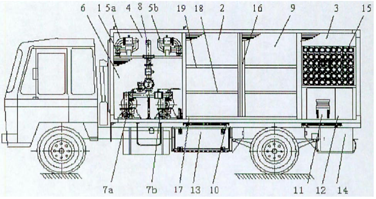
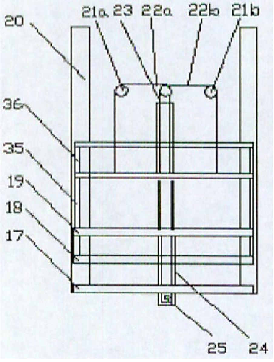
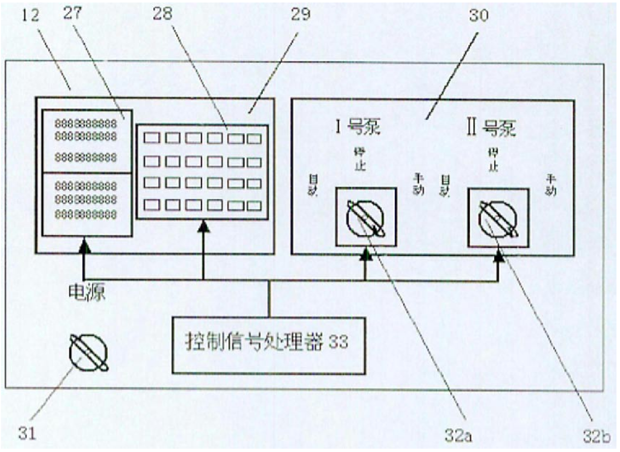
The utility model relates to a field oil receiving and sending oil operation vehicle, which is mainly used for setting up digital field oil depots. The shelter for oil delivery operation is divided into front cabin, middle cabin and rear cabin. The interior of the front cabin is divided into upper and lower floors. The upper layer is the crane tube room, and the lower layer is the pump room. There are two sets of pipeline systems and an electrostatic oil spill alarm system inside. There are two sliding doors on the top of the crane tube room that can be retracted freely. The middle cabin is a tank room for storing soft oil tanks and a set of hydraulic lifting system; the rear cabin is divided into upper and lower layers. It is divided into squares of the same size for storing polyurethane oil hoses. The lower layer is divided into two identical spaces, and the control cabinet, accessory box and two hydraulic trolleys are symmetrically placed. The control cabinet is driven by the oil pump motor. Controller and The fuel delivery controller is composed of two parts. The fuel delivery controller works under the unified and coordinated management of the CQM1H programmable control signal processor to realize the automatic control of sending and receiving oil. The invention reduces labor intensity, saves labor time, has a more reasonable structure, realizes automatic oiling under field conditions, and improves field oil supply capability.
Description
Field fuel receiving and dispatching vehicle technical field The invention relates to field oil sending and receiving operations, in particular to a field oil sending and receiving operation vehicle, which is mainly used for setting up digital field oil depots and providing oil support for combat troops under field conditions. Background technique The existing field oil supply of the group army is to use the "campaign field oil depot" (see the "Field Oil Equipment and Application" textbook, Beijing Military Region Oil Training Brigade, March 2003 edition), which consists of three identical units, each unit Capacity 400 meters 3 , each unit sends and receives oil, stores oil, and transports and loads it on a fully loaded and unloaded vehicle-mounted pallet, and the parts of sending and receiving oil and oil storage are concentrated in a combined compartment. Its combined compartment includes a set of engine pump sets and internal pipelines, placed in the rear compartment o...
Claims
Login to View More Application Information
Patent Timeline
 Patent Type & Authority Patents(China)
IPC IPC(8): B60P3/22B60P1/44
Inventor 李连聪张文峰刘永明王国水裴英民陈涛张波郇栋
Owner 中国人民解放军北京军区油料训练大队
Features
- R&D
- Intellectual Property
- Life Sciences
- Materials
- Tech Scout
- Unparalleled Data Quality
- Higher Quality Content
- 60% Fewer Hallucinations
Learn More Browse by: Latest US Patents, China's latest patents, Technical Efficacy Thesaurus, Application Domain, Technology Topic, Popular Technical Reports.
© 2025 PatSnap. All rights reserved.Legal|Privacy policy|Modern Slavery Act Transparency Statement|Sitemap|About US| Contact US: help@patsnap.com


