Scanning imaging seeker optical machine scanning component digital subdivision circuit
A technology of scanning imaging and headlight, which is applied in the direction of weapon accessories, optical radiation measurement, and offensive equipment, can solve the problems of complex conditioning circuits, poor anti-interference ability, and low control accuracy, and achieve strong anti-interference ability and self-adaptive ability Strong, high-precision signal processing effect
Active Publication Date: 2012-10-03
CHINA AIR TO AIR MISSILE INST
View PDF0 Cites 2 Cited by
- Summary
- Abstract
- Description
- Claims
- Application Information
AI Technical Summary
Problems solved by technology
Its disadvantages are: the conditioning circuit is complex, the control accuracy is not high, the anti-interference ability is poor, the circuit needs to be adjusted one by one for each seeker, and the versatility is poor
Method used
View moreImage
Smart ImageViewing Examples

Examples
Embodiment Construction
Login to View More PUM
 Abstract
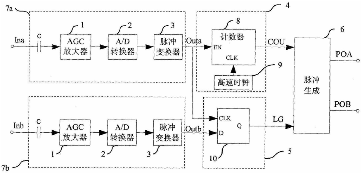
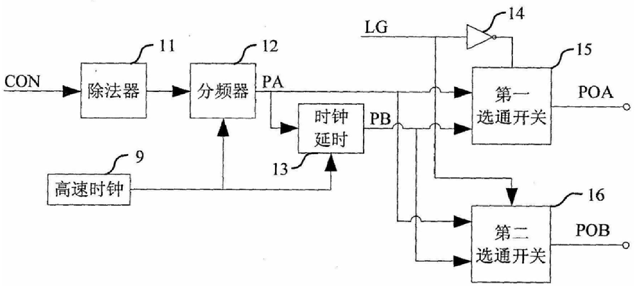
The invention belongs to the information processing technology of the infrared air-to-air missile seeker, and relates to the improvement of the subdivision circuit of the light-mechanical scanning component of the scanning imaging seeker. The digital subdivision circuit of the optical-mechanical scanning component of the scanning imaging seeker is characterized in that it consists of two signal conditioning circuits with the same structure, a frequency detection circuit [4], a phase detection circuit [5] and a pulse generation circuit [ 6]; the signal conditioning circuit is composed of a DC blocking capacitor C, an AGC amplifier [1], an A / D converter [2], and a pulse converter [3]; the frequency detection circuit [4] is composed of a counter [8] and a high-speed clock [9]; the phase detection circuit [5] is composed of a D flip-flop [10]; the pulse generating circuit [6] is composed of a divider [11], a frequency divider [12], a clock delay [13], a NOT gate [14], the first gating switch [15], the second gating switch [16] form. The invention has high signal processing precision, strong anti-interference ability, simple circuit, small size and high reliability; it reduces the difficulty of system debugging and improves the debugging efficiency.
Description
Scanning imaging seeker optical machine scanning component digital subdivision circuit technical field The invention belongs to the information processing technology of the infrared air-to-air missile seeker, and relates to the improvement of the subdivision circuit of the light-mechanical scanning component of the scanning imaging seeker. Background technique A new generation of air-to-air missiles marked by infrared imaging has been gradually equipped in recent years abroad. Some of them use line-scanning imaging technology. The signal processing technology of the optical-mechanical scanning component is relatively mature, but it is kept secret. China has been engaged in the development of optical-mechanical scanning components since the end of the 1990s, but the application of infrared imaging air-to-air missiles is still in the preliminary stage. At present, the signal processing of optical-mechanical scanning components for missiles is still dominated by analog circuit...
Claims
Login to View More Application Information
Patent Timeline
 IPC IPC(8): G01J5/00F41G7/22
Inventor 徐佩孟卫华魏新武陈晓曾孟庆超
Owner CHINA AIR TO AIR MISSILE INST
Features
- R&D
- Intellectual Property
- Life Sciences
- Materials
- Tech Scout
- Unparalleled Data Quality
- Higher Quality Content
- 60% Fewer Hallucinations
Learn More Browse by: Latest US Patents, China's latest patents, Technical Efficacy Thesaurus, Application Domain, Technology Topic, Popular Technical Reports.
© 2025 PatSnap. All rights reserved.Legal|Privacy policy|Modern Slavery Act Transparency Statement|Sitemap|About US| Contact US: help@patsnap.com