High reflective mirror laser backscatter measurement device
A measuring device and high reflective mirror technology, which is applied in the measurement of scattering characteristics, can solve the problems that have not been found in reports or literature, and achieve the effect of simple structure, low cost and improved measurement error
Inactive Publication Date: 2012-10-31
XIAN TECH UNIV
View PDF0 Cites 4 Cited by
- Summary
- Abstract
- Description
- Claims
- Application Information
AI Technical Summary
Problems solved by technology
The project team of this invention has searched domestic and foreign patent documents and published journal papers, and has not found any reports or documents closely related to the present invention.
Method used
View moreImage
Smart ImageViewing Examples

Examples
Embodiment 1
Embodiment 2
Embodiment 3
Login to View More PUM
| Property | Measurement | Unit |
|---|---|---|
| reflectance | aaaaa | aaaaa |
Abstract
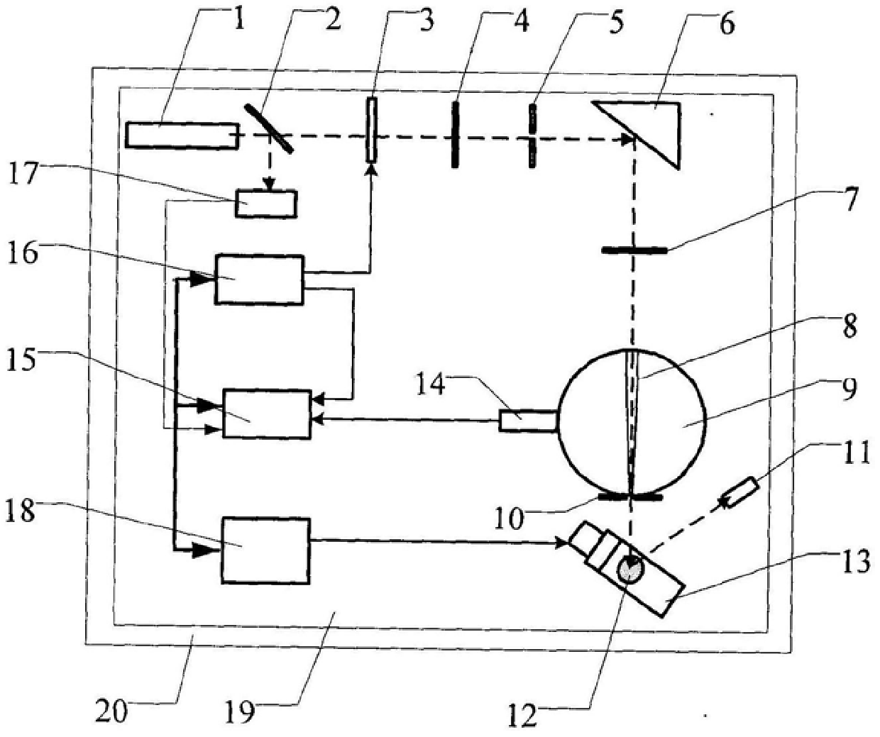
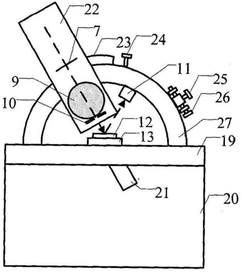
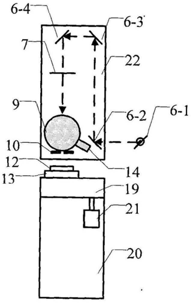
The utility model relates to a laser backscattering measurement device of a high reflection mirror, which belongs to the field of laser gyroscope testing. Split the laser light, detect the reflected light in real time to obtain the fluctuation information of the laser power, and send it to the differential end of the lock-in amplifier to deduct the influence of the light source fluctuation on the measured value; after the transmitted light is modulated and the optical components are adjusted, it is incident at an adjustable angle When it reaches the surface of the high reflector to be tested, the reflected light is absorbed by the light trap, and the backscattered light with the incident light as the optical axis is collected by the integrating sphere through a small hole solid angle, and converted into an electrical signal and sent to the differential end of the lock-in amplifier The second is sent to the computer through lock-in amplification processing. The measured sample moves with the computer-controlled electric console to complete the measurement of backscattered light intensity at different points, and obtains a two-dimensional distribution map. The problem of difficult measurement of weak backscattered light intensity is solved. It realizes the accurate measurement and automatic measurement of laser backscattering of high reflective mirrors, and can also measure the backscattering of high reflective mirrors or ultra-smooth surfaces for other purposes. It can be widely used in laser gyroscope production and scientific research.
Description
High reflective mirror laser backscatter measurement device technical field The invention belongs to the technical field of laser gyro testing, and relates to backscattering measurement of a high reflection mirror used in a laser gyro resonator cavity, in particular to a laser backscattering measurement device for a high reflection mirror. Background technique A typical laser gyro system has a polygonal (usually regular quadrilateral) optical resonant cavity. The high reflection mirror is the key optical component of the resonant cavity, and its reflectivity is generally as high as 99.99%. The two beams of light waves propagating counterclockwise in the resonator are not coupled to each other. The rotation of the laser system causes a Doppler frequency difference between the two beams of light waves. The difference is proportional to the rotation speed. Using this principle to Measure the angular rotational velocity to obtain the precise coordinates of the spatial position...
Claims
Login to View More Application Information
Patent Timeline
 Patent Type & Authority Patents(China)
IPC IPC(8): G01N21/47
Inventor 刘卫国高爱华徐昌杰秦文罡弥谦杭凌侠
Owner XIAN TECH UNIV
Features
- R&D
- Intellectual Property
- Life Sciences
- Materials
- Tech Scout
- Unparalleled Data Quality
- Higher Quality Content
- 60% Fewer Hallucinations
Learn More Browse by: Latest US Patents, China's latest patents, Technical Efficacy Thesaurus, Application Domain, Technology Topic, Popular Technical Reports.
© 2025 PatSnap. All rights reserved.Legal|Privacy policy|Modern Slavery Act Transparency Statement|Sitemap|About US| Contact US: help@patsnap.com