Forming tool and forming method for circumferential non-closed variable-cross-section cylindrical part

A technology of variable cross-section and parts, applied in the field of compound forming of sheet metal and pipe fittings, to achieve the effects of simplifying forming process, reducing manufacturing cost and improving utilization rate

Active Publication Date: 2017-01-25
天津天锻航空科技有限公司
View PDF10 Cites 4 Cited by
  • Summary
  • Abstract
  • Description
  • Claims
  • Application Information

AI Technical Summary

Problems solved by technology

[0005] Adopting the forming tooling and forming method that can be used for circumferential non-closed variable cross-section cylindrical parts can not only solve the current situation that the existing tubular internal high pressure forming can only form circumferentially closed parts, but also must realize the sealing between the part end and the sealing head

Method used


Image

  • Forming tool and forming method for circumferential non-closed variable-cross-section cylindrical part
  • Forming tool and forming method for circumferential non-closed variable-cross-section cylindrical part
  • Forming tool and forming method for circumferential non-closed variable-cross-section cylindrical part

Examples


Embodiment 1

[0039] Example 1, see Figure 1-Figure 7 ,

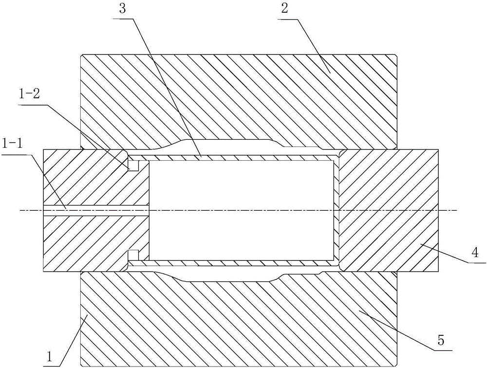
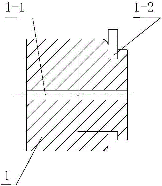
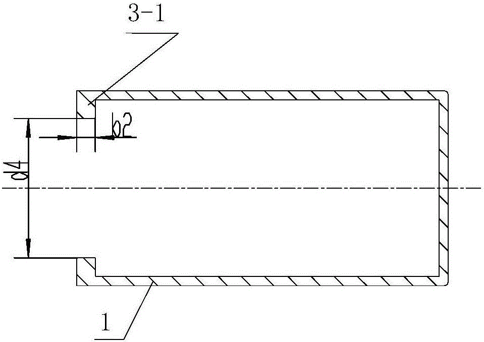
[0040] Tooling for forming cylindrical parts with non-closed variable cross-section in the circumferential direction, including a first sealing head 1, a second sealing head 4, a liquid-filled bladder 3, an upper mold 2 and a lower mold 5, and the first sealing head is provided with a liquid filling device. A liquid inlet 1-1 and an annular groove 1-2 for accommodating a liquid-filled bag, one end of the liquid-filled bag is an open end, and a sealing flange 3-1 for connection and sealing is formed on the open end, so The opening end of the liquid-filled bag is set on the first sealing head, and is embedded in the groove 1-2 of the first sealing head through the sealing flange, and the liquid-filled bag is located by the first sealing head 1, the second In the mold cavity that sealing head 4, upper mold 2 and lower mold 5 constitute.

[0041] In this embodiment, the width b1 of the annular groove on the first sealing head ≤ the wi...

Embodiment 2

[0051] Example 2, see Figure 1-Figure 3 , Figure 8 ,

[0052] A method for forming a circumferential non-closed variable-section cylindrical part using tooling for forming a circumferential non-closed variable-section cylindrical part, comprising the following steps:

[0053] S1. Install the lower mold, upper mold, first sealing head, liquid-filled bladder and second sealing head on the forging machine tool according to the design requirements, the lower mold and the press table are fixed, and the upper mold moves up to the set height. The first sealing head on which the liquid-filled bladder is fixed moves away from the second sealing head, so that enough space is left between the upper mold and the lower mold to place the blank.

[0054] S2. The blank in this forming method is a flat sheet. First, roll the flat sheet into a cylindrical or semicircular shape by hand or machine. After rolling, wrap Teflon or plastic film on the outside of the blank to maintain the shape of...

Embodiment 3

[0058] Example 3, see Figure 1-Figure 3 , Figure 9 ,

[0059] Tooling for forming cylindrical parts with non-closed variable cross-section in the circumferential direction, including a first sealing head 1, a second sealing head 4, a liquid-filled bladder 3, an upper mold 2 and a lower mold 5, and the first sealing head is provided with a liquid filling device. A liquid inlet 1-1 and an annular groove 1-2 for accommodating a liquid-filled bag, one end of the liquid-filled bag is an open end, and a sealing flange 3-1 for connection and sealing is formed on the open end, so The opening end of the liquid-filled bag is set on the first sealing head, and is embedded in the groove 1-2 of the first sealing head through the sealing flange, and the liquid-filled bag is located by the first sealing head 1, the second In the mold cavity that sealing head 4, upper mold 2 and lower mold 5 constitute.

[0060] In this embodiment, the width b1 of the annular groove on the first sealing ...


PUM


Abstract

The invention relates to a forming tool and a forming method for a circumferential non-closed variable-cross-section cylindrical part. The forming tool is characterized by comprising a first sealing head, a second sealing head, a liquid filling bag, an upper die and a lower die, wherein the first sealing head is provided with a liquid inlet and an annular groove, one end of the liquid filling bag is an open end, the open end is provided with a sealing flange, the open end of the liquid filling bag is arranged on the first sealing head in a sleeving mode and is embedded into the groove of the first sealing head through the sealing flange, and the liquid filling bag is located in the die cavity formed by the first sealing head, the second sealing head, the upper die and the lower die. The forming tool has the advantages that peculiar shaped part forming machining can be simplified, the material and device utilization rate and the forming part machining precision are remarkably improved, and the manufacturing costs are reduced. Blanks used by the forming method can be circumferentially closed tubular products or cylindrical parts and can be also a circumferentially opened tubular blanks having a certain overlapping amount or planar plates, and a machining application range is wide.

Description

technical field [0001] The invention belongs to the technical field of compound forming of metal sheets and pipe fittings, and in particular relates to a forming tool and a forming method for cylindrical parts with non-closed variable cross-section in the circumferential direction. Background technique [0002] Liquid-filled pipe forming uses pipe as a blank, and high-pressure liquid is applied inside to press the pipe into the cavity of the mold to obtain the desired shape of pipe parts. Liquid-filled sheet metal forming uses a flat sheet, and applies high-pressure liquid to one or both sides of the sheet to make the material fit the mold and finally form the desired part. Usually, the liquid-filled forming of pipes requires that the billet is a whole pipe that is circumferentially closed and can withstand a certain high pressure, and there is also a certain requirement for the length of the billet, which needs to be sealed by both ends during the forming process. However,...

Claims


Application Information

Patent Timeline
Patent Type & Authority Applications(China)
IPC IPC(8): B21J5/04B21J5/02B21J13/02
CPCB21J5/02B21J5/04B21J13/02
Inventor 施立军苏俊明张淳郎利辉
Owner 天津天锻航空科技有限公司
Why Eureka
Try Eureka