Vehicular emergency hammer

A safety hammer and hammer head technology, which is applied in vehicle safety arrangement, pedestrian/passenger safety arrangement, vehicle components, etc., can solve problems such as unclear sending of distress signals, inconvenient cutting of winding objects, locking and unable to open, etc., to achieve Reduce the time to clear escape obstacles, improve space utilization, and improve the efficiency of escape

Inactive Publication Date: 2017-01-25
卢平
View PDF7 Cites 0 Cited by
  • Summary
  • Abstract
  • Description
  • Claims
  • Application Information

AI Technical Summary

Problems solved by technology

In the event of a rollover, collision, water entry, etc., the car door may be locked and cannot be opened, and the safety belt of the car will also fail to open; prior art China, the Chinese patent No. CN205468931U discloses an emergency car lock for automobiles. Life-saving device, including life-saving hammer main body, first life-saving hammer, second life-saving hammer, life-saving hammer connecting handle, connecting handle, safety belt cutter, cutter cover handle, multiple connecting bolts, installation frame, multiple installation through holes and multiple clamping parts; the main body of the life-saving hammer is connected with the first life-saving hammer, the second life-saving hammer and the connecting handle of the life-saving hammer, the safety belt cutter is set on the connecting handle of the life-saving hammer through the cutter cover handle, and the connecting handle is connected by connecting bolts. The life-saving hammer is connected to the handle, and the installation frame is installed in the car through the installation through hole and bolts; the clamping part is set on the installation frame, and the main body of the life-saving device is embedded in the installation frame through the clamping part
When using this device, there are problems such as inconvenient cutting of winding objects, unclear sending of distress signals, etc., and this technical solution does not propose a solution

Method used


Image

  • Vehicular emergency hammer
  • Vehicular emergency hammer
  • Vehicular emergency hammer

Examples


Embodiment Construction

[0020] The technical solution of the present invention will be further described below in conjunction with the accompanying drawings, but the scope of protection is not limited to the description.

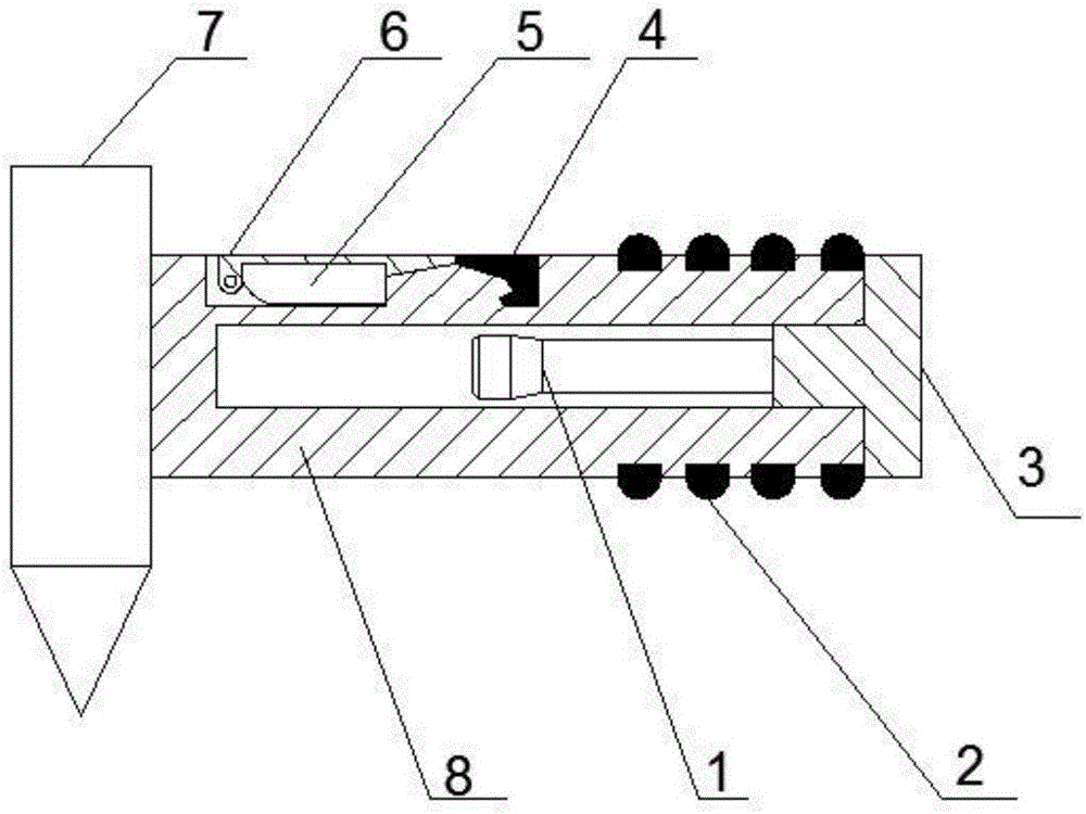
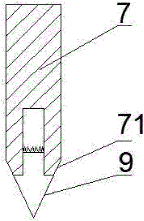
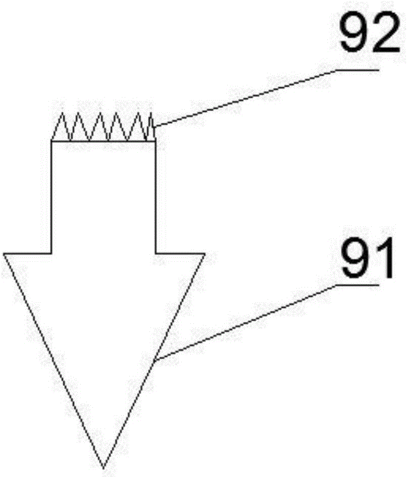
[0021] Such as figure 1 , figure 2 , image 3 The vehicle-mounted safety hammer shown includes a hammer head 7 and a handle 8. The hammer head 7 is installed on the handle 8. The hammer head 7 has a tapered head and a cylindrical tail, and the handle 8 is hollow inside. The cylindrical tubular structure, the side of the handle 8 is provided with a handle 6, the handle 6 is hinged on the handle 8, the handle 6 is provided with a blade 5, and the tail of the handle 8 is provided with a tailstock 3. A flashlight 1 is installed on the tailstock 3 .

[0022] The tup 7 is installed on the handle 8, and the tup 7 is used to hit the window glass. In order to break the glass, the tup 7 is a tapered head and a cylindrical structure at the tail. The tup 7 is tapered at the head, which is ...


PUM


Abstract

The invention discloses a vehicular emergency hammer. The emergency hammer comprises a hammer head and a handle, wherein the hammer head is arranged on the handle; the hammer head has a conical-head and cylindrical tail structure, and the handle has a hollow cylindrical tubular structure; a knife handle is arranged on the side face of the handle, and is hinged to the handle; a blade is arranged on the knife handle; a tail seat is arranged at the tail part of the handle, and is provided with a torch. According to the vehicular emergency hammer, rotatable knife handle and blade are arranged on the handle, so that a safety belt or other winding objects can be cut off by adopting a pressing mode, and the time for cleaning escape barriers can be reduced; and by adopting the hollow handle and torch, space utilization rate can be increased, illumination is facilitated, an SOS signal can be sent out, and the escape success rate can be increased. The vehicular emergency hammer is simple in structure and low in manufacture cost, and is easy for transformation implementation and application.

Description

technical field [0001] The invention relates to the technical field of emergency lifesaving equipment manufacturing, in particular to a vehicle-mounted safety hammer. Background technique [0002] With the improvement of living standards, people mostly use automobiles to travel, and automobiles are a closed structure, and due to various subjective or objective factors, there is a certain degree of danger in the driving of automobiles. In the event of a rollover, collision, water entry, etc., the car door may be locked and cannot be opened, and the safety belt of the car will also fail to open; prior art China, the Chinese patent No. CN205468931U discloses an emergency car lock for automobiles. Life-saving device, including life-saving hammer main body, first life-saving hammer, second life-saving hammer, life-saving hammer connecting handle, connecting handle, safety belt cutter, cutter cover handle, multiple connecting bolts, installation frame, multiple installation throug...

Claims


Application Information

Patent Timeline
Patent Type & Authority Applications(China)
IPC IPC(8): B60R21/02A62B3/00
CPCB60R21/02A62B3/00
Inventor 卢平
Owner 卢平
Why Eureka
Try Eureka