A helical rotary engine

A rotary engine and solenoid technology, used in rotary piston engines, engine components, combustion engines, etc., can solve the problems that the axial thrust cannot completely cancel each other, affect the service life of the engine bearing, and the structure is complex, so as to reduce heat consumption. The effect of dispersing, easily sealing, and reducing the volume

Active Publication Date: 2019-06-07
罗显平
View PDF10 Cites 0 Cited by
  • Summary
  • Abstract
  • Description
  • Claims
  • Application Information

AI Technical Summary

Problems solved by technology

[0008] Especially when the gas output provided by the air compressor or steam generator is small, a helical rotary engine is required to form a gas helical rotary engine or a steam helical rotary engine with a net output power of less than 1000 kilowatts. Performance, such as using a labyrinth seal will be difficult, making its structure complex
[0009] In a turbine engine, when the built-in axial flow compressor is coaxial with the power turbine, when the gas expands to do work, two axial thrusts in opposite directions will be generated on the two axial cross-sections of the combustion chamber. Due to the special structure of the turbine engine , the two cross-sections in the axial direction are difficult to be equal, so that the two axial thrusts in opposite directions cannot completely cancel each other out, and the rotating shaft bearing has to bear a large axial thrust, so special bearings should be provided for the thrust, which will obviously affect the engine bearings service life

Method used


Image

  • A helical rotary engine
  • A helical rotary engine
  • A helical rotary engine

Examples


Embodiment Construction

[0042] The present invention will be further described below in conjunction with the accompanying drawings.

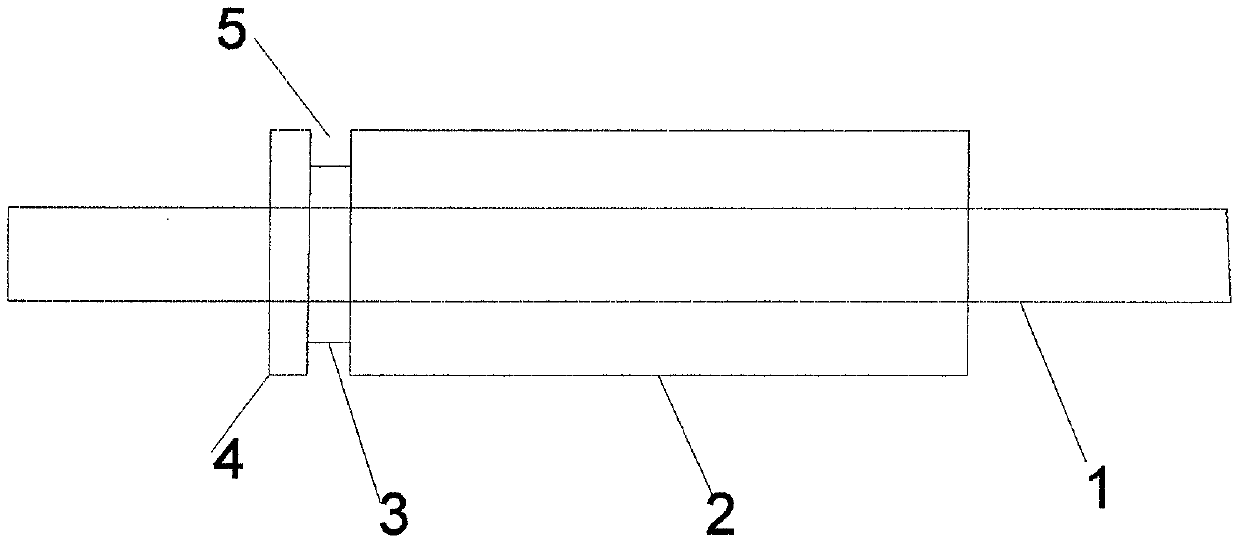
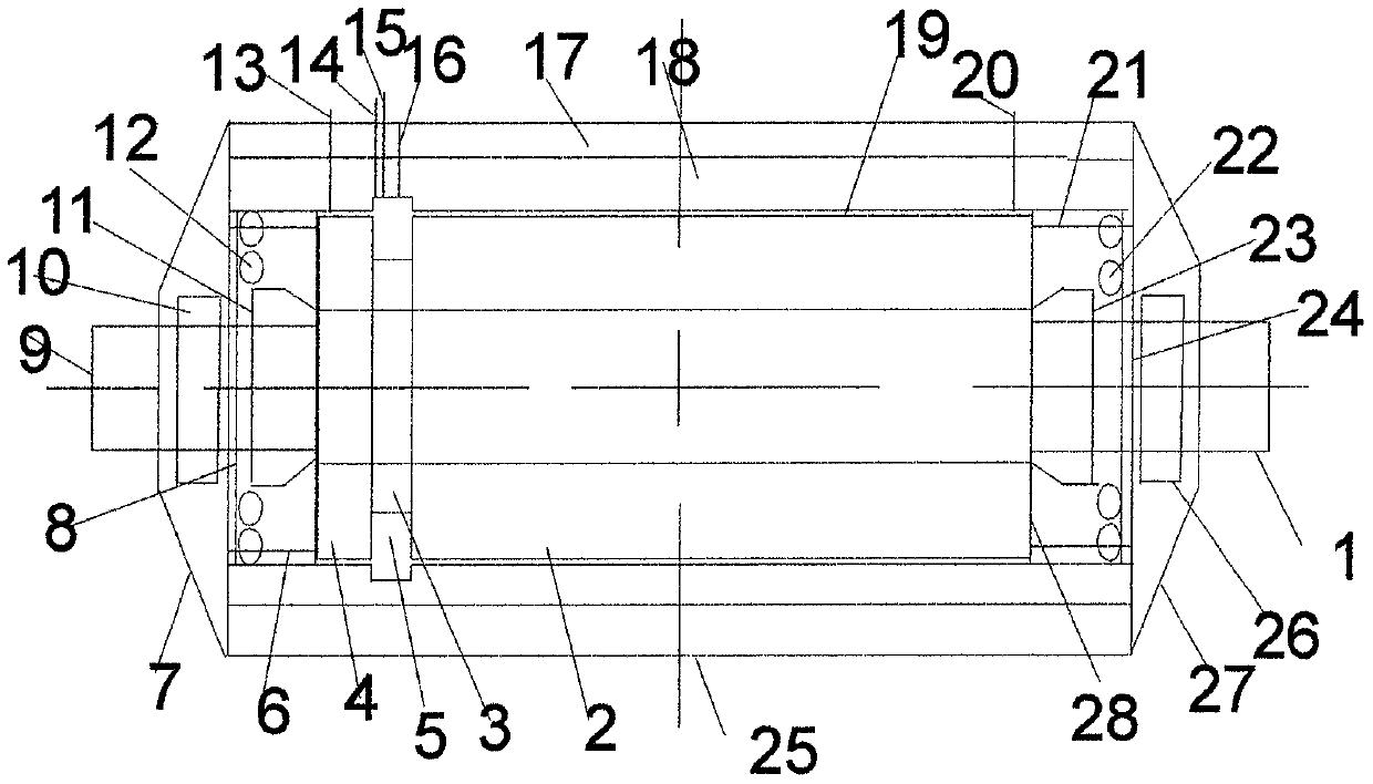
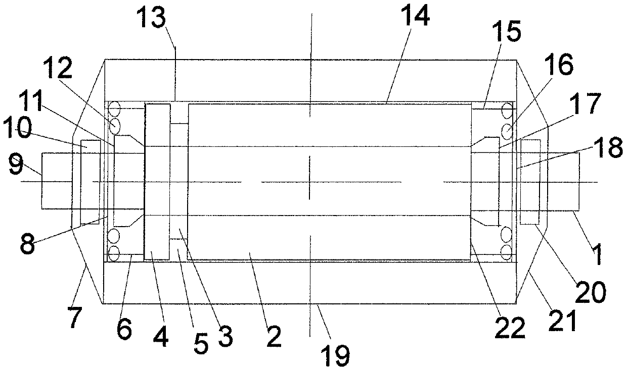
[0043] The rotating body of the spiral tube rotor is made on the same cylinder as a whole of the head cylinder, neck cylinder, and built-in spiral tube cylinder, or the left built-in spiral tube cylinder, neck cylinder, and neck are made on the same cylinder. The whole body of the inner cylinder and the right built-in helical tube cylinder, the helical tube for converting fluid energy is arranged on the surface layer of the built-in helical tube cylinder.

[0044] The rotating body of the rotor is a whole made of a head cylinder, a neck cylinder and a built-in solenoid cylinder on the same cylinder, referred to as a single-ended solenoid rotor. Tube rotor engine. The connected head cylinder is mainly used to counteract the axial thrust generated by the fluid in the cavity of the neck cylinder.

[0045] The rotating body of the rotor is made of the left built-in spira...


PUM


Abstract

The invention discloses a solenoid rotor composed of a rotation shaft and a rotating body and a fuel gas solenoid rotor engine and a steam rotor solenoid rotor engine which take the structural form of being provided with a single-end solenoid rotor or double-end solenoid rotor as a core. The rotor rotating body is an entirety of a head cylinder, a neck cylinder and a built-in solenoid cylinder which are manufactured on a same cylinder or an entirety of a left built-in solenoid cylinder, a neck cylinder and a right built-in solenoid cylinder which are manufactured on a same cylinder, and a solenoid used for converting fluid energy is arranged on the surface layer of the built-in solenoid cylinder. Therefore, the solenoid rotor engines have the structural forms similar to those of a motor stator, a rotor and an end cover and have the technical advantages of being simple and compact in structure, durable in bearing, easy to seal, high in cycle thermal efficiency, low in manufacturing cost, high in installed power and the like, and the fuel gas solenoid rotor engine and the steam rotor solenoid rotor engine can be widely assembled and applied to the civil and military fields of power generation, airplanes, ships, power, automobiles and the like.

Description

technical field [0001] The invention relates to an engine, in particular to a helical tube rotor engine. Background technique [0002] A turbine is an engine that uses fluid to impinge on the rotation of the impeller to generate power. It is mainly divided into four types: gas turbine engine, steam turbine engine, water turbine engine (ie water turbine), and compressed air turbine engine. The gas turbine engine is composed of two parts: an air compressor and a turbine rotor engine. The air compressor is connected to the turbine rotor engine for power, and is also connected to the combustion chamber to form a gas generator. The steam turbine engine is also composed of a steam generator and a turbine rotor engine, wherein the steam generator is connected to the steam chamber of the turbine rotor engine. The turbine engines of the prior art are widely used in civil and military fields such as power generation, aircraft, ships, and power, and play a very important role. [000...

Claims


Application Information

Patent Timeline
Patent Type & Authority Patents(China)
IPC IPC(8): F02B55/02F02B53/00F02B55/14F02B53/08F02B55/08F02F11/00F02B77/11F01P1/00F01C1/107F01C21/08F01C21/10F01C19/08F01C21/06
CPCF01C1/107F01C19/085F01C21/06F01C21/08F01C21/104F01P1/00F02B53/00F02B53/08F02B55/02F02B55/08F02B55/14F02B77/11F02F11/007Y02T10/12
Inventor 罗显平
Owner 罗显平
Why Eureka
Try Eureka