Hydraulic tank

A technology of hydraulic oil tank and hydraulic oil, applied in the direction of fuel supply tank device, mechanical equipment, etc., can solve the problem of inconvenience of the driver's work, and achieve the effect of intelligent automatic oil replenishment, convenient operation and simple structure

Active Publication Date: 2018-02-06
LIUZHOU LIUGONG EXCAVATORS +2
View PDF4 Cites 0 Cited by
  • Summary
  • Abstract
  • Description
  • Claims
  • Application Information

AI Technical Summary

Problems solved by technology

The above-mentioned process of replenishing hydraulic oil to the hydraulic oil tank brings inconvenience to the driver's work

Method used


Image

  • Hydraulic tank
  • Hydraulic tank
  • Hydraulic tank

Examples


Embodiment Construction

[0014] Hereinafter, the present invention will be described in detail in conjunction with the accompanying drawings and embodiments. However, the present invention is not limited to the following examples.

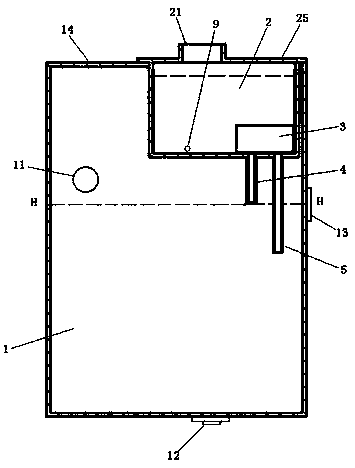
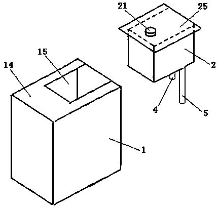
[0015] Such as figure 1 , 2 , 3, the hydraulic oil tank of this embodiment includes a main box body 1, the main box body 1 is a box shape, and is provided with an oil suction port 12 and an oil return port 11, and the top surface 14 of the main box body 1 An opening 15 is provided, hydraulic oil is housed in the main box body 1, and a liquid level gauge 13 is provided on the side of the main box body 1, and the hydraulic oil in the main box body 1 can be observed from the liquid level gauge 13. the oil level, figure 1 The H-H position shown is the reference oil level position of the hydraulic oil in the hydraulic oil tank in the non-working state.

[0016] The hydraulic oil tank of this embodiment also includes an oil replenishment device, which is arranged inside the ...


PUM


Abstract

Provided is a hydraulic oil tank. A tank body of an oil supplementing is in a sealed tank body shape, the top of the tank body is provided with an oil adding port and an oil adding port cover, hydraulic oil is contained in the tank body, the tank body is fixed to the position of an opening of a main tank body to enter the main tank body, the top surface of the tank body is fixedly connected with the top surface of the main tank body, the bottom of the tank body is further provided with a control valve, the bottom of the control valve is provided with a first valve port and a second valve port, the bottom of the tank body is provided with two through holes, the first valve port and the second valve port of the control valve penetrate out of the bottom of the tank body through the positions of the two through holes respectively, and a first through pipe and a second through pipe are vertically arranged at the bottom of the tank body. The first valve port is fixedly connected with the upper end of the first through pipe, the second valve port is fixedly connected with the upper end of the second through pipe, a port at the lower end of the second through pipe is lower than the position of a port at the lower end of the first through pipe, and the control valve is a two-position four-way solenoid valve having a cutoff and communication function. The hydraulic oil tank has the advantages of being simple and compact in structure and convenient to operate and achieving an intelligent function of automatically supplementing oil.

Description

technical field [0001] The invention relates to the technical field of engineering machinery, in particular to a hydraulic oil tank. Background technique [0002] When the construction machinery equipment is working, driven by the hydraulic pump, the hydraulic oil flows out from the oil suction port of the hydraulic oil tank and drives hydraulic components such as cylinders and motors to work through the hydraulic oil circuit, and the returned hydraulic oil returns through the oil return port of the hydraulic oil tank. Hydraulic tank. Therefore, during the working process of construction machinery and equipment, the hydraulic oil in the hydraulic oil tank fluctuates. It should be ensured that the hydraulic oil tank should be able to accommodate the hydraulic oil flowing into the hydraulic oil tank in the system when the hydraulic system stops working, and the hydraulic oil tank should be in the working process. Maintain proper fluid levels. Therefore, the regular maintenan...

Claims


Application Information

Patent Timeline
Patent Type & Authority Patents(China)
IPC IPC(8): F15B1/26
CPCF15B1/26
Inventor 雷艳梅邵以东覃敏珍
Owner LIUZHOU LIUGONG EXCAVATORS
Why Eureka
Try Eureka