Method for forming cutter machining tracks on NURBS combined curved surface

A technology of processing trajectory and processing direction, which is applied in the field of tool processing trajectory generation on NURBS composite surfaces, can solve the problems of affecting the appearance and processing quality of the workpiece, not being able to process, and the single topology of the trajectory.

Active Publication Date: 2017-01-25
DALIAN UNIV OF TECH
View PDF5 Cites 15 Cited by
  • Summary
  • Abstract
  • Description
  • Claims
  • Application Information

AI Technical Summary

Problems solved by technology

Although the isoparameter method is easy to implement, the processing efficiency is low
In addition, the splitting process will leave tool marks at the joints of the dough pieces, which will affect the appearance and processing quality of the workpiece
The above two type

Method used


Image

  • Method for forming cutter machining tracks on NURBS combined curved surface
  • Method for forming cutter machining tracks on NURBS combined curved surface
  • Method for forming cutter machining tracks on NURBS combined curved surface

Examples


Embodiment Construction

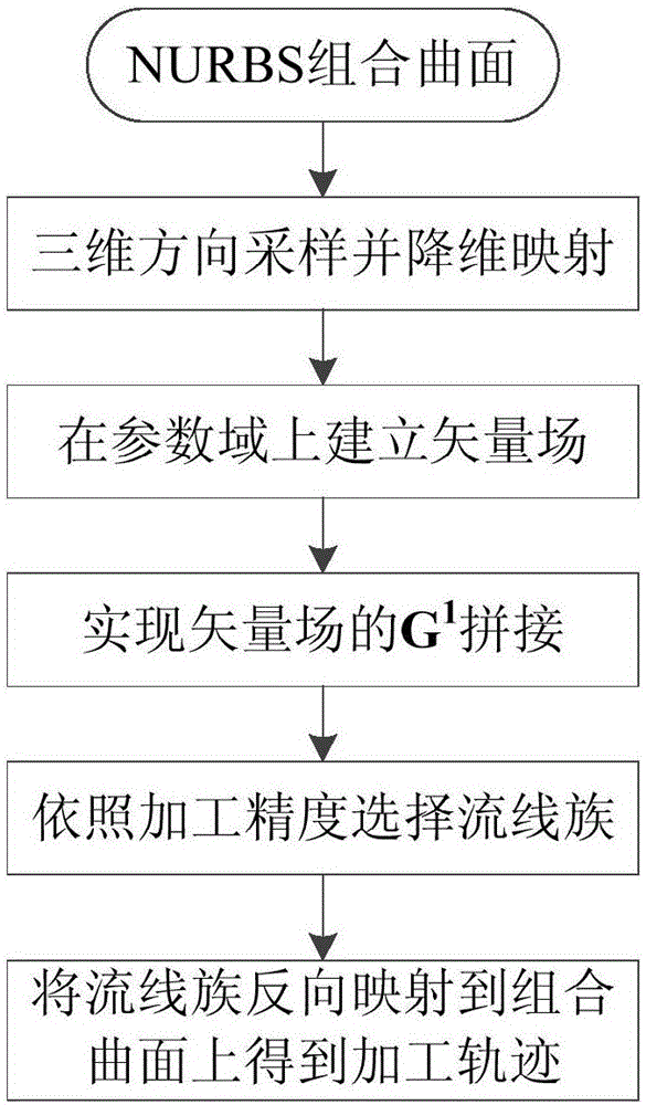
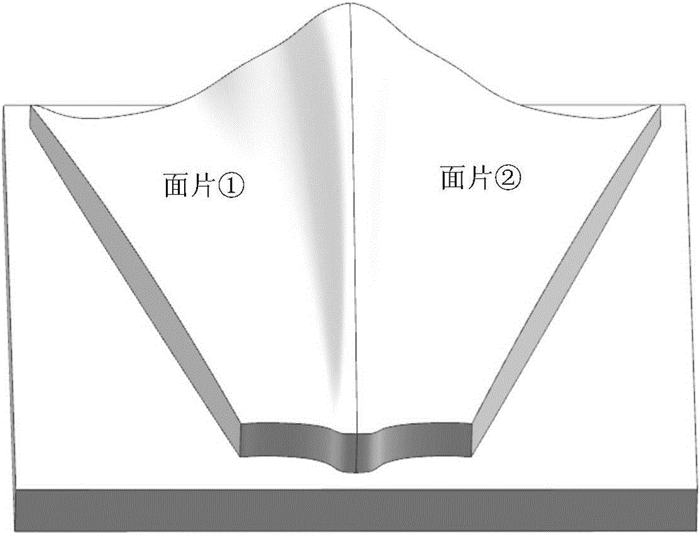
[0043] The flow chart of a method for generating tool machining paths on NURBS composite surfaces is as follows: figure 1 shown. In order to highlight the characteristics of the present invention to generate the tool path, here with C 1 Take the continuous two-face NURBS compound surface as an example (see figure 2 ), with reference to the accompanying drawings and implementation steps the specific implementation process of the present invention is described in detail:

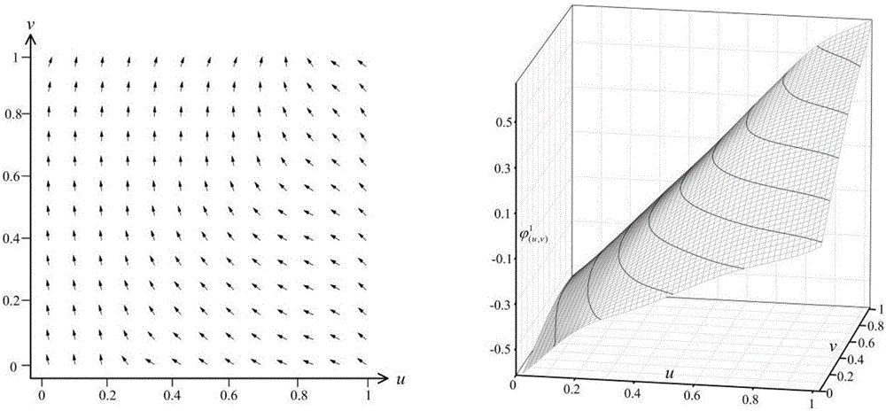
[0044] (a) Carry out grid division for each patch, and the optimal cutting direction at each grid point is selected as the maximum bandwidth direction at that point, and the expression of this direction in the parameter domain is as follows:

[0045] a = cos - e 1 ...


PUM


Abstract

The invention relates to a method for forming cutter machining tracks on an NURBS combined curved surface and belongs to the technical field of numerical control machining. According to the method, by splicing vector fields, the problem that the smooth and topologically controllable cutter machining tracks are formed on a C1 continuous NURBS combined curved surface is solved. The method comprises the following steps: carrying out sampling on each surface piece of the combined curved surface along the feeding direction, respectively, so as to obtain the feeding direction of each surface piece in a corresponding parameter domain; establishing a localized feeding vector field based on a stream function represented by a sample-B primary function polynomial on each surface piece parameter domain, and regulating the control parameters close to the borders of adjacent vector fields, so as to realize the G1 splicing of the vector fields; and selecting required series flow lines from the G1 continuous combined vector field according to the machining precision requirement, and mapping the series flow lines to the combined curved surface, so as to obtain the feeding tracks required by the machining. According to the method, the uniform expression meeting machining track line groups of the C1 continuous combined curved surface is achieved, and smooth and various-form machining tracks can be formed.

Description

technical field [0001] The invention relates to a method for generating tool machining tracks on a NURBS combined curved surface, belonging to the technical field of numerical control machining. Background technique [0002] Due to its advantages in expressing complex or detailed shapes, composite surfaces are more and more widely used in CAD / CAM systems. In order to achieve high-quality and efficient machining of curved surfaces, the planning of the tool path is particularly important. However, the current processing methods for composite surfaces are very limited. B.K.Choi et al. proposed to intersect the composite surfaces with a set of parallel planes, and use the obtained intersection lines as machining trajectories (Compound surface modeling and machining. Comput-Aided Des1988,20( 3): 127-136.). This method has a wide range of applications and strong reliability. After continuous improvement by researchers, it is still the main method for processing composite surface...

Claims


Application Information

Patent Timeline
IPC IPC(8): G05B19/4097
CPCG05B19/4097
Inventor 孙玉文孙硕学徐金亭郭东明
Owner DALIAN UNIV OF TECH
Why Eureka
Try Eureka