A Reentry Trajectory Optimal Design Method for Radial No-Fly Zones

A technology of re-entry trajectory and optimization design, applied in the field of flight, can solve the problem of oversimplification of the model, it is difficult to reflect the radiation pattern close to the exposure danger to a certain extent, etc., to achieve the effect of small threat integration and good detection and tracking.

Active Publication Date: 2019-02-05
NAT UNIV OF DEFENSE TECH
View PDF2 Cites 0 Cited by
  • Summary
  • Abstract
  • Description
  • Claims
  • Application Information

AI Technical Summary

Problems solved by technology

For the radar coverage area, it is obvious that the above model is oversimplified, and it is difficult to reflect the characteristics that the radiation type can be close to a certain extent and is related to the exposure risk

Method used


Image

  • A Reentry Trajectory Optimal Design Method for Radial No-Fly Zones
  • A Reentry Trajectory Optimal Design Method for Radial No-Fly Zones
  • A Reentry Trajectory Optimal Design Method for Radial No-Fly Zones

Examples


Embodiment Construction

[0017] The present invention will be further described below in conjunction with the accompanying drawings and specific embodiments.

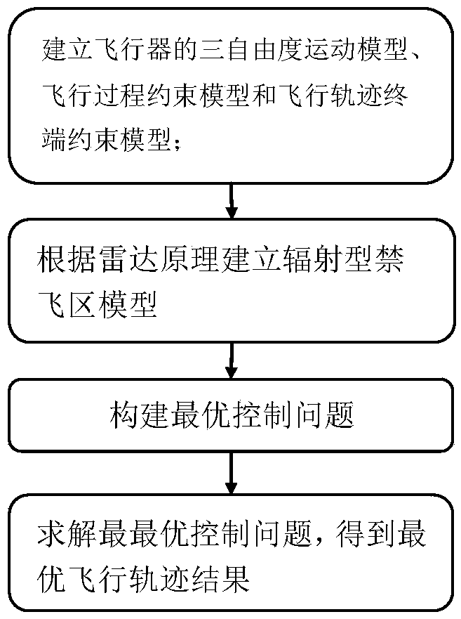
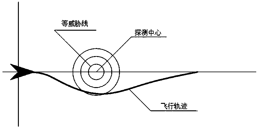
[0018] The present invention establishes the threat quantification model per unit time of any point in the radiation-type no-fly zone, describes the threat of the radiation-type no-fly zone, and then transforms the constraint of the no-fly zone into a performance index function related to the threat integral according to the model; finally Use the Gauss pseudospectral method to solve this optimization problem, the specific process is as follows figure 1 shown. figure 2 It is a schematic plan view of the radiation-type no-fly zone in the present invention. The detection center in the figure is the isothreat line expanded by the center of the circle, and the flight path of the aircraft is shown in the figure.

[0019] For ease of understanding the present invention, concrete model and principle are described as follows below:

[0020] 1. Hyper...


PUM


Abstract

Belonging to the technical field of flight, the invention relates to an optimal design method for reentry trajectory in the radioactive prohibited area comprising the steps of S1, setting up aircraft three-degree freedom motion model, flight process constraint model and flight trajectory terminal constraint model; S2, constructing radioactive prohibited area model (img file='DDA0001082531380000011.TIF' wi='350' he='105' / ), wherein, Rk refers to threat coefficient, C refers to ratio coefficient, K / N refers to radar signal-noise ratio, and Rd refers to radar ranging coverage; threats of any point in the radioactive prohibited area in unit time are quantized to describe degree of threat in the radioactive prohibited area; S3, deeming integral of threat coefficient of the radioactive prohibited area model as property indicator function and aircraft as control object to construct optimal control problem; S4, solving the optimal control problem in S3 by Guass pseudo-spectral method to draw the optimal flight trajectory of aircraft to break through the radioactive prohibited area. The optimal design method for reentry trajectory in the radioactive prohibited area enhances capacity of strategic delivery and breakthrough of hypersonic speed aircraft and facilitates aircraft to break through radar detection and tracking.

Description

technical field [0001] The invention belongs to the technical field of flight, and mainly relates to a reentry trajectory optimization design method for a radial no-fly zone. Background technique [0002] In recent years, with the rapid development and maturity of hypersonic gliding vehicle related technologies, and for the future hypersonic gliding vehicle to be put into use better, more and more attention has been paid to its trajectory optimization, especially with no-fly zones Constrained Trajectory Optimization Problem. Due to the complex and harsh operating environment of hypersonic vehicles, this kind of trajectory optimization problem needs to consider not only the constraints of the no-fly zone, but also other constraints during the flight process, such as overload, aerodynamic heat, dynamic pressure, etc. etc., which makes the trajectory optimization problem with no-fly zone constraints more complicated. [0003] Broadly speaking, a no-fly zone refers to an area ...

Claims


Application Information

Patent Timeline
Patent Type & Authority Patents(China)
IPC IPC(8): G05D1/10
CPCG05D1/101
Inventor 葛健全杨涛汪艮泉丰志伟李正楠许强强
Owner NAT UNIV OF DEFENSE TECH
Why Eureka
Try Eureka